Iqpump, Control circuit terminal connections, Iqpump drive factory default – Yaskawa iQpump Controller User Manual User Manual
Page 51: 3 control wiring, Pump motor
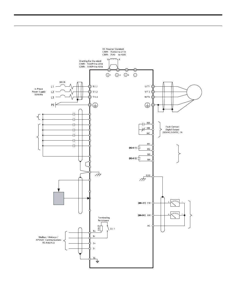
2.3 Control Wiring
YASKAWA TM.iQp.06 iQpump Controller User Manual
51
◆ Control Circuit Terminal Connections
■
iQpump Drive Factory Default
Connections to iQpump drive terminals for the default factory settings are shown in
.
Figure 2.6 Default Terminal Connections
P
P
P
P
24
S3 (H1-01)
S2
S1
SC
S4 (H1-02)
S5 (H1-03)
S6 (H1-04)
S7 (H1-05)
SN
Feedback Device
(e.g Pressure Transducer)
NOT USED
RUN
Multi-function
Digital Inputs
24VDC, 8 mA
Digital Inputs
24VDC, 8mA
SP 24VDC +/-20%, 8mA
+V +15VDC +/-10%, 20mA
A1 0 to +10VDC, 20 kW
Ω*
A2 4 to 20mA, 250W
Ω*
[0 to +/-10VDC, 20kW
Ω**]
Multi-function Analog Input 1 (H3-09)
AC
EXT. PUMP FAULT
FAULT RESET
MULTI SP 1
HAND MODE
DISABLE PRE-CHG
Feedback Device
4-20mA
2 Wire Connection
Output
Supply
E(G)
Multi-function
Digital Outputs
250VAC, 30VDC, 1A
PUMP 2 CONTROL
PUMP 3 CONTROL
M
Pump Motor
Multi-function
Analog Outputs
0 to +10 VDC, 2 mA
4-20 mA, 500
Ω
iQpump