Introduction to stateful failover states – H3C Technologies H3C WX6000 Series Access Controllers User Manual
Page 606
50-2
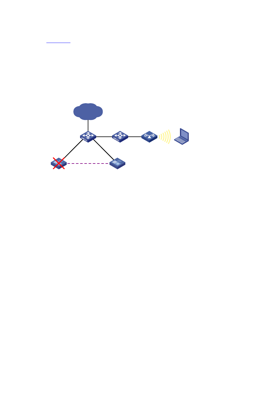
The stateful failover feature (supporting portal service currently) is introduced to meet the requirement.
, two ACs that are enabled with stateful failover are deployed in the network. You need to
specify a VLAN on the two ACs as the backup VLAN, and add the interfaces between the ACs to the
backup VLAN. The backup VLAN is like a failover link, through which the two ACs exchange state
negotiation messages periodically. After the two ACs enter the synchronization state, they back up the
service entries of each other to ensure that the service entries on them are consistent. If one AC fails,
the other AC, which has already backed up the service information, can take over the services, thus
avoiding service interruption.
Figure 50-2 Network diagram for stateful failover
GE1/0/2
Tagged VLAN: 2
AC 1
Internet
Host
AC 2
Failover link
AP
VLAN 2
GE1/0/2
Tagged VLAN: 2
Introduction to Stateful Failover States
The stateful failover states include:
Silence: Indicates that the device is just started and waiting for the stable running of the system, or
the state between synchronization and independence.
Independence: Indicates that the silence timer expires, but no backup link to any other device is
established.
Synchronization: Indicates that state negotiation with another device is complete and ready for
data backup.
The following figure shows state relations.