Legacy interrupts, Legacy interrupts –4 – Altera Arria V Hard IP for PCI Express User Manual
Page 198
11–4
Chapter 11: Interrupts
Interrupts for Root Ports Using the Avalon-ST Interface to the Application Layer
Arria V Hard IP for PCI Express
December 2013
Altera Corporation
User Guide
f
For more information about implementing the MSI-X capability structure, refer
Section 6.8.2. of th
.
Legacy Interrupts
Legacy interrupts are signaled on the PCI Express link using message TLPs that are
generated internally by the Arria V Hard IP for PCI Express IP core. The
tl
_
app_int_sts_vec
input port controls interrupt generation. To use legacy
interrupts, you must clear the
Interrupt Disable
bit, which is bit 10 of the
Command
register (
). Then, turn off the
MSI Enable
describes 3 example implementations; 1 in which all 32 MSI messages are
allocated and 2 in which only 4 are allocated.
MSI interrupts generated for Hot Plug, Power Management Events, and System
Errors always use TC0. MSI interrupts generated by the Application Layer can use
any Traffic Class. For example, a DMA that generates an MSI at the end of a
transmission can use the same traffic control as was used to transfer data.
Interrupts for Root Ports Using the Avalon-ST Interface to the
Application Layer
In Root Port mode, the Arria V Hard IP for PCI Express IP core receives interrupts
through two different mechanisms:
■
MSI—Root Ports receive MSI interrupts through the Avalon-ST RX TLP of type
MWr
. This is a memory mapped mechanism.
■
Legacy—Legacy interrupts are translated into TLPs of type
Message
Interrupt
which is sent to the Application Layer using the
int_status[3:0]
pins.
Normally, the Root Port services rather than sends interrupts; however, in two
circumstances the Root Port can send an interrupt to itself to record error conditions:
■
When the AER option is enabled, the
aer_msi_num[4:0]
signal indicates which
MSI is being sent to the root complex when an error is logged in the AER
Capability structure. This mechanism is an alternative to using the
serr_out
signal. The
aer_msi_num[4:0]
is only used for Root Ports and you must set it to a
constant value. It cannot toggle during operation.
■
If the Root Port detects a Power Management Event, the
pex_msi_num[4:0]
signal
is used by Power Management or Hot Plug to determine the offset between the
base message interrupt number and the message interrupt number to send
through MSI. The user must set
pex_msi_num[4:0]
to a fixed value.
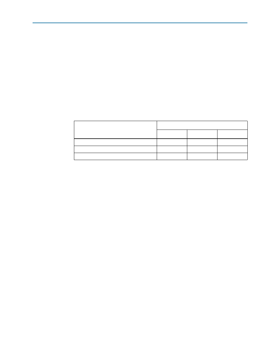
Table 11–1. MSI Messages Requested, Allocated, and Mapped
MSI
Allocated
32
4
4
System error
31
3
3
Hot plug and power management event
30
2
3
Application Layer
29:0
1:0
2:0