Chaining dma descriptor tables, Chaining dma descriptor tables –12, Table 17–6 – Altera Arria V Hard IP for PCI Express User Manual
Page 234
17–12
Chapter 17: Testbench and Design Example
Chaining DMA Design Examples
Arria V Hard IP for PCI Express
December 2013
Altera Corporation
User Guide
describes the fields in the DMA read status high register. All of these fields
are read only.
Chaining DMA Descriptor Tables
describes the Chaining DMA descriptor table which is stored in the BFM
shared memory. It consists of a four-dword descriptor header and a contiguous list of
<n> four-dword descriptors. The Endpoint chaining DMA application accesses the
Chaining DMA descriptor table for two reasons:
■
To iteratively retrieve four-dword descriptors to start a DMA
■
To send update status to the RP, for example to record the number of descriptors
completed to the descriptor header
Each subsequent descriptor consists of a minimum of four dwords of data and
corresponds to one DMA transfer. (A dword equals 32 bits.)
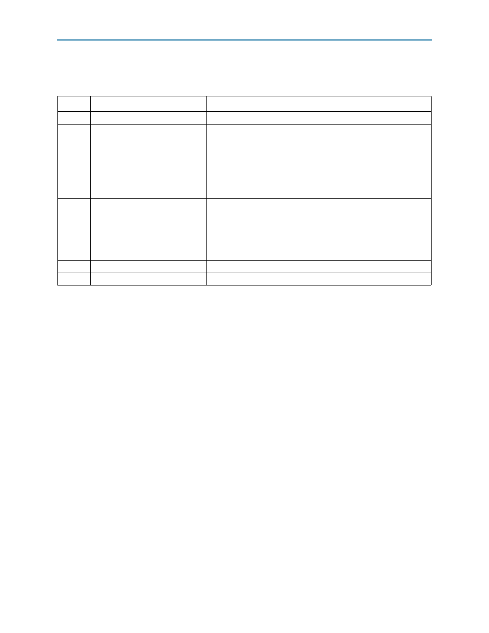
Table 17–6. Fields in the DMA Read Status High Register
Bit
Field
Description
[31:24]
Reserved
—
[23:21]
Max Read Request Size
The following encodings are defined:
■
001 128 bytes
■
001 256 bytes
■
010 512 bytes
■
011 1024 bytes
■
100 2048 bytes
[20:17]
Negotiated Link Width
The following encodings are defined:
■
0001 ×1
■
0010 ×2
■
0100 ×4
■
1000 ×8
16
Read DMA Descriptor FIFO Empty
Indicates that there are no more descriptors pending in the read DMA.
[15:0]
Read DMA EPLAST
Indicates the number of the last descriptor completed by the read DMA.