Setting the breaker duty monitoring function – Basler Electric BE1-851 User Manual
Page 114
(
)
operations
*#
I
max
D
errupt
int
=
Equation 6-4. Dmax Set by Number of Operations
The setting is in terms of primary amps (the relay multiples by the CT ratio before doing calculations).
If the breaker-monitoring mode is set to sum
I
2
, the relay internally squares the setting that is entered for
Dmax. The relay sums the square of the currents interrupted and it will set the breaker duty alarm when
the sum exceeds the square of the Dmax setting. The approach to set Dmax is to select the maximum
number of operations at some current level and enter a Dmax calculated by the equation:
(
)
5
0
2
.
errupt
int
operations
*#
I
max
D
=
Equation 6-5. Dmax Set Using Square Root Factor
Again, the setting is in terms of primary amps. The 0.5 power (i.e., square root factor) shown above for
the Dmax setting is to compensate for the fact that the relay internally squares the Dmax that is entered.
When testing the relay by injecting currents into the relay, the values in the duty registers should be read
and recorded before the start of testing. Once testing is complete and the relay is returned to service, the
registers should be reset to the original pre-test values. A block accumulation logic input may be used
when testing so that simulated breaker duty is not added to the duty registers. The Block Accumulation
Logic function is an OR logic term (e.g., IN1 or VO7) which blocks the breaker monitoring logic when
TRUE (1). Block Accumulation Logic is set to zero to disable blocking. When breaker monitoring is
blocked (logic expression equals 1), breaker duty is not accumulated.
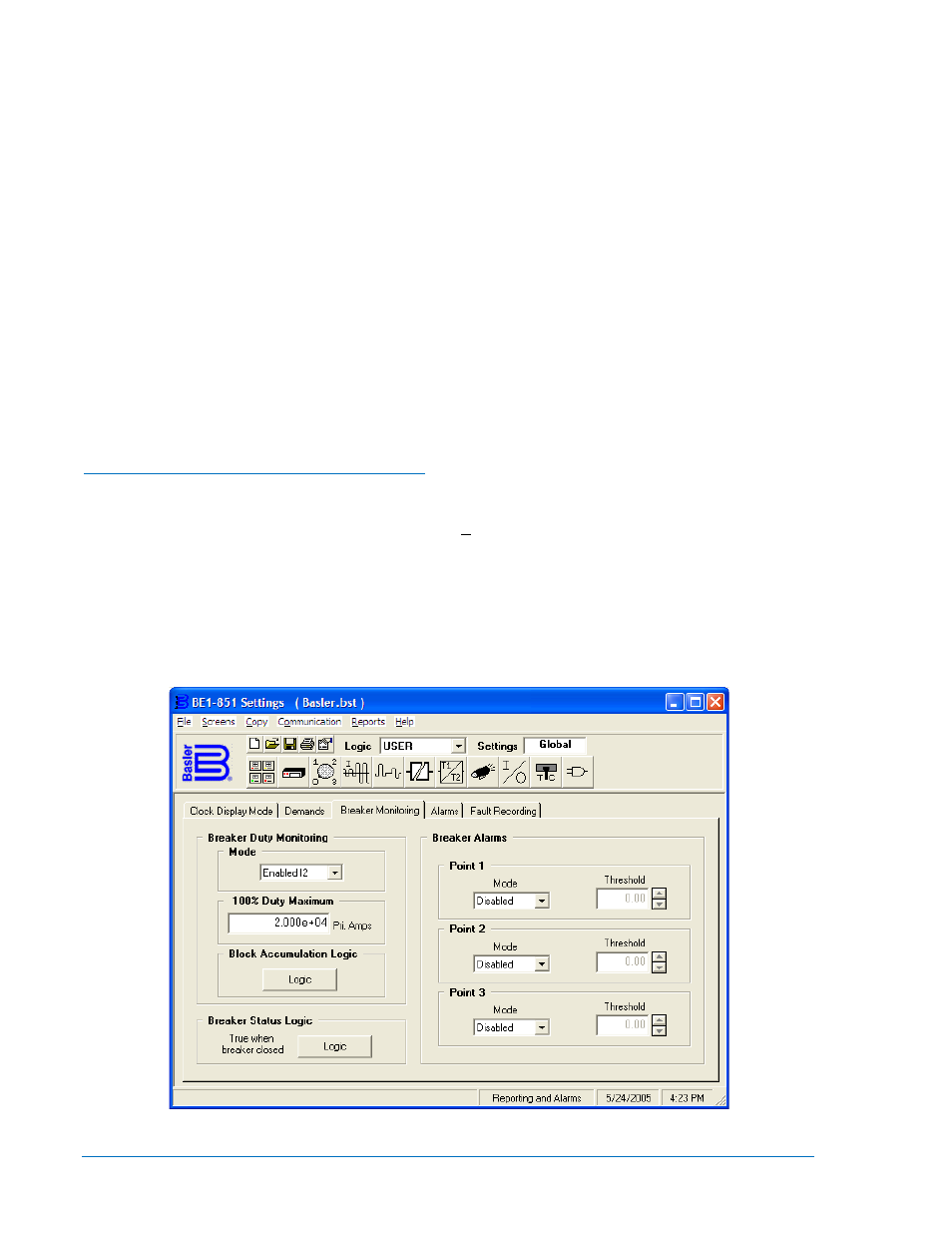
Setting the Breaker Duty Monitoring Function
Breaker Duty Monitoring settings are made using BESTCOMS. Figure 6-5 illustrates the BESTCOMS
screen used to select settings for the Breaker Duty Monitoring function. To open the Reporting and
Alarms screen, select Reporting and Alarms from the Screens pull-down menu. Then select the Breaker
Monitoring tab. Settings may also be made using the SB-DUTY ASCII command.
At the top left of the screen is a pull-down menu labeled Logic. This menu allows viewing of the
BESTlogic settings for each preprogrammed logic scheme. User must be selected on this menu in order
to allow changes to be made to the mode and inputs of the function/element.
Using the pull-down menus and buttons, make the application appropriate settings to the Breaker Duty
Monitoring function. Table 6-6 summarizes the Breaker Duty Monitoring settings.
Figure 6-5. Reporting and Alarms Screen, Breaker Monitoring Tab
6-12
BE1-851 Reporting and Alarms
9289900990 Rev R