Retrieving and resetting alarm reports, Table 6-15. programmable alarm settings -32 – Basler Electric BE1-851 User Manual
Page 134
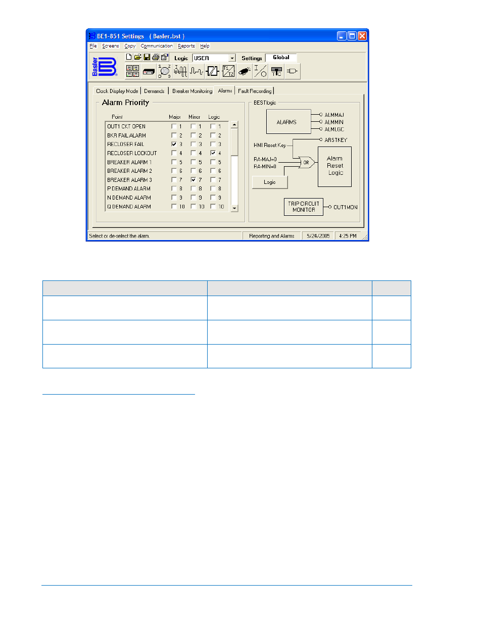
Figure 6-19. Reporting and Alarms Screen, Alarms Tab
Table 6-15. Programmable Alarm Settings
Setting
Range/Purpose
Default
Major alarm points (drives Major Alarm LED
and ALMMAJ logic variable).
List of alarm functions per Table 6-13
25
Minor alarm points (drives Minor Alarm LED
and ALMMIN logic variable).
List of alarm functions per Table 6-13
29
Logic alarm points (drives ALMLGC logic
variable).
List of alarm functions per Table 6-13
0
Retrieving and Resetting Alarm Reports
When an alarm condition occurs, the appropriate front panel LED lights and HMI Screen 1.3 is displayed.
(See Section 10, Human-Machine Interface, for more information about automatic display priority logic.)
The HMI display scrolls between displaying all active alarm points. This includes alarms that are not
programmable (relay trouble alarms). Any latched alarms that are not currently active can be reset by
pressing the HMI Reset key. Refer to Table 6-13 for the list of latching alarm points and self-clearing
alarm points.
The Reset key of the HMI is context sensitive. That is, the functionality depends upon what screen is
currently being displayed. BESTlogic variable RSTKEY takes advantage of this to allow the front panel
Reset key on the relay to be used in the programmable logic scheme when the Alarms screen 1.3 is
active. An example of the use of this logic variable is to break the seal-in for a logic expression. The logic
expression can be programmed so that the seal-in function uses VO13, VO14, or VO15. If the virtual
output expression is included in one of the programmable alarm masks, the automatic display priority
logic will cause the display to go to the Alarms screen 1.3. When the Reset key is pressed on the front of
the relay, the RSTKEY logic variable is asserted and the logic expression seal-in is broken. See Section
8, Application, Application Tips, for more information. Figure 6-20 shows the alarm reset logic.
Logic variables for ALMMAJ, ALMMIN, and ALMLGC can also be set to operate any of the output
contacts to give an indication that an alarm condition exists. Section 7, BESTlogic Programmable Logic,
provides more details about this feature.
6-32
BE1-851 Reporting and Alarms
9289900990 Rev R