Contact-sensing inputs, Turn-on voltage, Input burden – Basler Electric BE1-851 User Manual
Page 26: Recognition time, Irig, Contact-sensing inputs -10, Contact inputs recognition time -10, Irig -10, Table 1-1. contact-sensing turn-on voltages -10, Table 1-2. contact-sensing input burden -10
Contact-Sensing Inputs
Turn-On Voltage
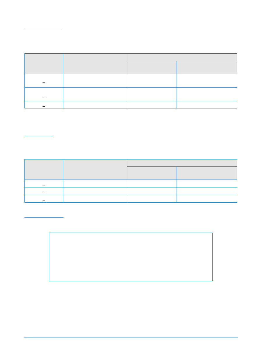
Contact-sensing turn-on voltages are listed in Table 1-1.
Table 1-1. Contact-Sensing Turn-On Voltages
Style Option
Nominal Input Voltage
Contact-Sensing Turn-On Voltage *
Jumper Installed
(Low Position) †
Jumper Not Installed
(High Position) †
xxx1xxx
48 Vdc or 125 Vac/dc
26 to 38 Vdc
69 to 100 Vdc
56 to 97 Vac
xxx2xxx
125/250 Vac/dc
69 to 100 Vdc
56 to 97 Vac
138 to 200 Vdc
112 to 194 Vac
xxx3xxx
24 Vdc
n/a
Approx. 5 Vdc
*
AC voltage ranges are calculated using the default recognition time (4 ms) and debounce time (16 ms).
† Voltage ranges depend on jumper configurations. See Section 3, Input and Output Functions, Contact-
Sensing Inputs.
Input Burden
Burden values shown in Table 1-2 assume nominal value of input voltage applied.
Table 1-2. Contact-Sensing Input Burden
Style Option
Nominal Input Voltage
Burden
Jumper Installed
(Low Position)
Jumper Not Installed
(High Position)
xxx1xxx
48 Vdc or 125 Vac/dc
22 kΩ
53 kΩ
xxx2xxx
125/250 Vac/dc
66 kΩ
123 kΩ
xxx3xxx
24 Vdc
n/a
6 kΩ
Recognition Time
Programmable ................................................................ 4 to 255 ms
NOTE
All timing specifications are for the worst-case response. This includes output
contact operate times and standard BESTlogic operation timing but excludes
input debounce timing and non-standard logic configurations. If a non-standard
logic scheme involves feedback, then one or more BESTlogic update rate
delays must be included to calculate the worst-case delay. An example of
feedback is virtual outputs driving function block inputs. For more information,
see Section 7, BESTlogic Programmable Logic.
IRIG
Standard ......................................................................... 200-98, Format B002
Input Signal ..................................................................... Demodulated (dc level-shifted digital signal)
Logic-High Voltage ......................................................... 3.5 Vdc, minimum
Logic-Low Voltage .......................................................... 0.5 Vdc, maximum
Input Voltage Range ....................................................... +10 to −10 Vdc
Resistance ...................................................................... Nonlinear, approximately 4 kΩ at 3.5 Vdc,
approximately 3 kΩ at 20 Vdc
1-10
BE1-851 General Information
9289900990 Rev R