Basler Electric BE1-851 User Manual
Page 126
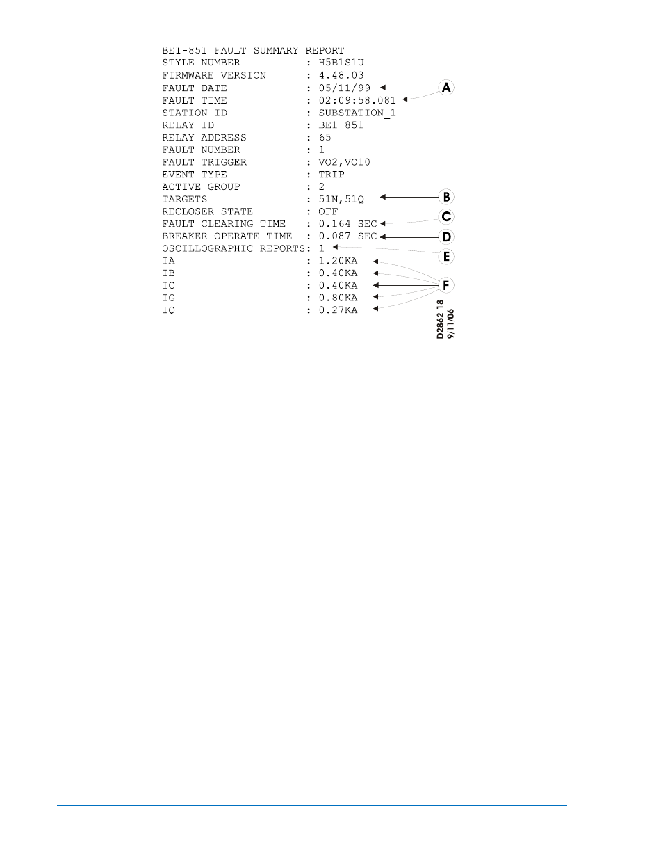
Style Number. This line reports the style number of the relay.
Firmware Version. This line reports the version of firmware that the relay holds.
Fault Date and Time. These lines report the date and the time of the initial trigger of the event. This is
based on either the pickup logic expression or the logic trigger expression becoming TRUE as defined by
the SG-TRIGGER command. Refer to Figure 6-8 and Table 6-8, call-out A.
Station ID and Relay ID. These lines report station and device identifier information as defined by the SG-
ID command.
Relay Address. This line reports the communications port address from which the report was requested.
The relay address number is assigned using the SG-COM command, described in Section 11, ASCII
Command Interface.
Fault Number. This line reports the sequential number (from 1 to 255) assigned to the report by the BE1-
851.
Fault Trigger. This line reports the logic variables in the pickup or logic trigger expressions that became
TRUE to trigger the recording of the event.
Event Type. This line reports the type of event that occurred. There are five fault event categories.
•
Trip: A fault was detected as defined by the pickup expression and the relay tripped to clear the
fault.
•
Pickup: A fault was detected as defined by the pickup expression but the relay never tripped
indicating that the fault was cleared by another device.
•
Logic: A fault report was recorded by the logic trigger expression but no fault was detected as
defined by the pickup expression.
•
Breaker Failure: A fault was detected as defined by the pickup expression and the breaker failure
trip became TRUE before the fault was cleared.
•
RF=TRIG: A fault report was recorded by the ASCII command interface.
Active Group. This line reports what setting group was active at the time that the fault occurred.
Targets. This line reports the targets that were logged to the fault report between the time that the trip
expression became TRUE until the end of the fault. Refer to Figure 6-8 and Table 6-8, call-out B.
Recloser State. This line reports the state of the recloser shot counter before the fault that triggered the
report.
Fault Clearing Time. This line reports the time from when the relay detected the fault until the relay
detected that the fault had cleared. Refer to Figure 6-8 and Table 6-8, call-out C.
6-24
BE1-851 Reporting and Alarms
9289900990 Rev R