General, Front panel display, Section 10 • human-machine interface -1 – Basler Electric BE1-851 User Manual
Page 231: General -1, Front panel display -1, Figure 10-1. be1-851 front panel hmi -1, Table 10-1. front panel hmi descriptions -1
SECTION 10 • HUMAN-MACHINE INTERFACE
General
This section provides a description of the BE1-851 human-machine interface and illustrates the menu
tree.
Front Panel Display
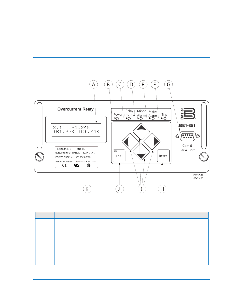
Figure 10-1 shows the front panel HMI for a BE1-851 relay in an H1 case configuration. The lettered
locations of Figure 10-1 correspond to the HMI descriptions of Table 10-1. F1 and S1 style relays have
the same controls and indicators with different layouts.
Figure 10-1. BE1-851 Front Panel HMI
Table 10-1. Front Panel HMI Descriptions
Locator
Description
A
Display - Two line by 16-character liquid crystal display (LCD) with backlighting. The LCD
is the primary source for obtaining information from the relay or when locally programming
settings to the relay. It displays the active logic scheme name, targets, metering values,
demand values, communication parameters, diagnostic information, and the menu tree
steps or branches.
B
Power LED - When this LED is ON, it indicates operating power is applied to the relay.
C
Relay Trouble LED - When this LED is ON, it indicates that the relay is off-line due to a
relay failure alarm. Refer to Section 6, Reporting and Alarms, for a description of all relay
failure alarm diagnostics.
9289900990 Rev R
BE1-851 Human-Machine Interface
10-1