Reclosing, Breaker failure, Reclosing -11 – Basler Electric BE1-851 User Manual
Page 315: Breaker failure -11, Figure 14-13. reclosing screen -11
Reclosing
Pull down the Screens menu and select Reclosing or click on the Reclosing icon that is shown
at the right margin of this paragraph. This screen has no folder tabs. It is labeled Reclosing.
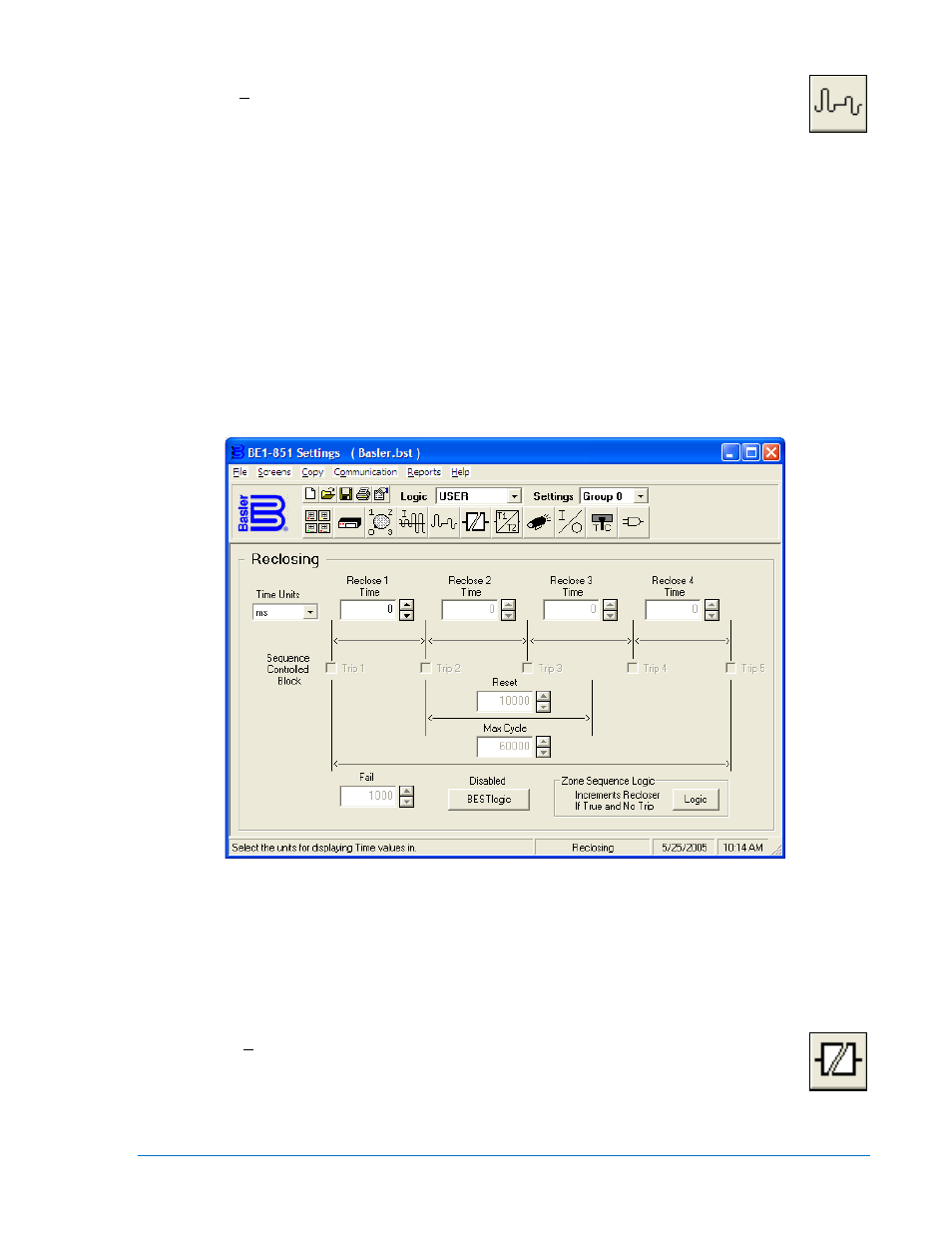
The reclosing function provides up to four reclosing attempts that can be initiated by a
protective trip or by one of the contact sensing inputs. (See Figure 14-13.) To set the actual reclose
sequence, first pull down the Time Units menu and set the units for time measurement. Notice that when
the Reclose 1 Time setting is zero, the Sequence Controlled Block (SCB), Trip 1 is grayed out. Set the
Reclose 1 Time for the first reclose time and the SCB window is now available. Enter the reclose times for
the remaining reclose attempts. The total time for all reclose attempts is cumulative. For example, the
second reclose attempt is the sum of Reclose 1 Time and Reclose 2 Time. Reclose three total time would
be the sum of the reclose time for three, two, and one. If you want to block the instantaneous or any other
protection element during reclose, check the SCB window or windows. If the 79C or 52 status is TRUE,
and the SCB is enabled (checked) for the next reclose attempt, the 79 SCB output becomes TRUE and
the output logic can be used to block the instantaneous element.
Set the reset time using the same unit of measure that was used for the reclosing attempts. Reset time is
how long you want the relay to remain reset before the relay returns to the initial state.
Set the maximum cycle time. Maximum cycle time limits the duration of a reclosing sequence as
determined from sequence initiation to automatic relay reset or lockout.
Figure 14-13. Reclosing Screen
Logic settings for the 79 reclosing function can be made by clicking on the BESTlogic button and with
your custom logic selected, select the mode and other input logic by using the Mode pull-down menu and
clicking on the logic inputs to set the logic.
To set the zone sequence coordination, click on the Zone-Sequence Logic button. When the Reclosing
dialog box opens, click on the logic diagram and set the logic.
Breaker Failure
Pull down the Screens menu and select Breaker Failure or click on the Breaker Failure icon
that is shown at the right margin of this paragraph. This screen has no folder tabs. It is labeled
Breaker Failure.
To set the time delay from when the breaker failure initiate is received and the trip output is asserted, first
pull down the Timer Setting Units menu (Figure 14-14) and set the units for time measurement. Then set
the Timer Setting Time.
9289900990 Rev R
BE1-851 BESTCOMS™ Software
14-11