Table 13-16. pickup and timer settings -8, Table 13-17. timing ranges -8, Table 13-18. timing ranges -8 – Basler Electric BE1-851 User Manual
Page 296
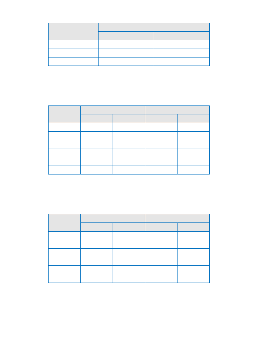
Table 13-16. Pickup and Timer Settings
Style Number
Commands
Phase
Neutral
x1xxxxx
S0-50TP=1.0A,0.0m
S0-50TN=1.0A,0.0m
x3xxxxx
S0-50TP=5.0A,0.0m
S0-50TN=1.0A,0.0m
x5xxxxx
S0-50TP=5.0A,0.0m
S0-50TN=5.0A,0.0m
Step 3:
Apply the appropriate current value to the Phase A input and measure the time between the
application of current and OUT1 closing. Verify that the timing is within the acceptance range
stated in Table 13-17.
Table 13-17. Timing Ranges
Style
Number
Current/Frequency
Timing Range
Phase
Neutral
Low Limit
High Limit
x1xxxxx
1.05A/50 Hz
1.05A/50 Hz
0.0 sec
0.1 sec
x1xxxxx
1.05A/60 Hz
1.05A/60 Hz
0.0 sec
0.083 sec
x3xxxxx
5.25A/50 Hz
1.05A/50 Hz
0.0 sec
0.1 sec
x3xxxxx
5.25A/60 Hz
1.05A/60 Hz
0.0 sec
0.083 sec
x5xxxxx
5.25A/50 Hz
5.25A/50 Hz
0.0 sec
0.1 sec
x5xxxxx
5.25A/60 Hz
5.25A/60 Hz
0.0 sec
0.083 sec
Step 4:
Apply the appropriate current value to the Phase A input and measure the time between the
application of current until OUT1 closes. Verify that the timing is within the acceptance range
stated in Table 13-18.
Table 13-18. Timing Ranges
Style
Number
Current/Frequency
Timing Range
Phase
Neutral
Low Limit
High Limit
x1xxxxx
1.5A/50 Hz
1.5A/50 Hz
0.0 sec
0.04 sec
x1xxxxx
1.5A/60 Hz
1.5A/60 Hz
0.0 sec
0.033 sec
x3xxxxx
7.5A/50 Hz
1.5A/50 Hz
0.0 sec
0.04 sec
x3xxxxx
7.5A/60 Hz
1.5A/60 Hz
0.0 sec
0.033 sec
x5xxxxx
7.5A/50 Hz
7.5A/50 Hz
0.0 sec
0.04 sec
x5xxxxx
7.5A/60 Hz
7.5A/60 Hz
0.0 sec
0.033 sec
Step 5:
Apply the appropriate current value to the Phase A input and measure the time between the
application of current and OUT1 closing. Verify that the timing is within the acceptance range
stated in Table 13-19.
13-8
BE1-851 Testing and Maintenance
9289900990 Rev R