Power-up, Communications, Style and serial number verification – Basler Electric BE1-851 User Manual
Page 290: Irig, Contact sensing input and output contacts, Power-up -2, Communications -2, Style and serial number verification -2, Irig -2, Contact sensing input and output contacts -2
Power-Up
Step 1:
Apply voltage to Power Terminals A6 and A7. Table 13-1 shows the appropriate voltage for
each style of relay.
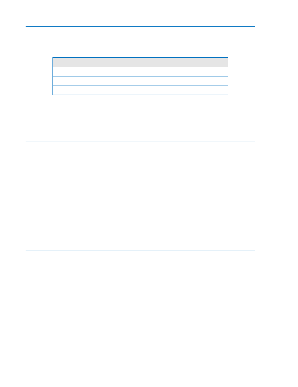
Table 13-1. Relay Voltages
Style Number
Voltage Input
xxx1xxx
48/125 Vac/dc
xxx2xxx
125/250 Vac/dc
xxx3xxx
24 Vdc
Step 2:
Verify that the Power LED is illuminated, the display backlight is lit, and characters are
displayed on the display. Upon power-up of the relay, a brief self-test is performed. During
this five-second test, all of the front panel LEDs will flash and the display will indicate each
step of the test followed by a screen showing the relay model number and software version.
Communications
Either a VT-100 terminal or a computer with a serial port and suitable communications software may be
used to communicate with any of the BE1-851 relay's three communications ports. The relay default
communications settings are: a baud rate of 9600, 8 data bits, 1 stop bit, parity - none and Xon/Xoff flow
control.
Step 1:
Connect the terminal cable to the rear RS-232 port on the relay.
Step 2:
Transmit the command “ACCESS=851” to the relay. The relay should respond with
“ACCESS GRANTED: GLOBAL”. Transmit “EXIT” after getting access.
Step 3:
Connect the terminal cable to the front RS-232 port on the relay.
Step 4:
Transmit the command “ACCESS=851” to the relay. The relay should respond with
“ACCESS GRANTED: GLOBAL”. Transmit “EXIT” after getting access.
Step 5:
Connect an RS-232/RS485 converter box to the RS-232 port on the terminal. Connect the
RS-485 output terminals of the converter box to the relay RS-485 terminals.
Step 6:
Transmit the command “ACCESS=851” to the relay. The relay should respond with
“ACCESS GRANTED: GLOBAL”. Transmit “EXIT” after getting access.
Style and Serial Number Verification
Over any communications port, transmit the command "RG-VER." The BE1-851 will respond with the
model number, style number, program version and date, boot code version and date, as well as the relay
serial number. Verify that the part, style, and serial numbers match the information on the relay front label.
IRIG
Step 1:
Connect a suitable IRIG source to the relay IRIG Terminals A1 and A2.
Step 2:
Upon receiving the IRIG signal, the relay clock will be set with the current time, month, and
day. This may be verified at Screen 4.5 on the front panel display or by transmitting “RG-
TIME” and “RG-DATE” to any of the relay communications ports.
Contact Sensing Input and Output Contacts
Step 1:
Apply voltage to the relay contact sensing inputs IN1, IN2, IN3, and IN4. Table 13-2 shows
the appropriate voltage to apply.
13-2
BE1-851 Testing and Maintenance
9289900990 Rev R