Function block logic settings, Output logic settings, Defining output operation – Basler Electric BE1-851 User Manual
Page 146: Function block logic settings -6, Output logic settings -6, Figure 7-3. 79 reclosing logic function block -6, Figure 7-4. virtual output logic -6
Function Block Logic Settings
Each BESTlogic function block is equivalent to its discrete device counterpart. For example, the
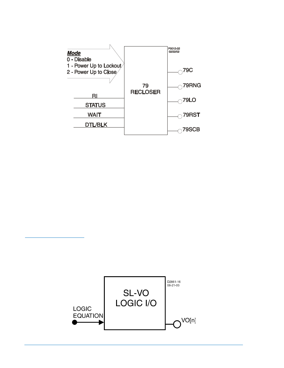
Reclosing Logic Function Block of Figure 7-3 has many of the characteristics of a BE1-79M Relay.
Figure 7-3. 79 Reclosing Logic Function Block
Before using a protection or control function block, two items must be set: the mode and the input logic.
Setting the Mode is equivalent to deciding which protection or control functions will be used in a logic
scheme. The input logic establishes control of a function block.
Mode and input logic information is contained in logic setting command strings. Depending on the
command, the mode setting can either enable or disable a logic input or determine how a function block
operates. Input logic defines which logic variables will control or disable a logic function. An example of an
input BLOCK logic equation is IN3+VO6. The IN3+VO6 expression indicates that the 51P function is
disabled when Input e (IN3) or Virtual Output 6 (VO6) is TRUE.
The AND operator may not be applied to the terms of an input logic equation. Any number of variables or
their inverse can be combined in a function block input logic expression. Section 4, Protection and
Control, provides detailed information about setting the logic for each function block.
Output Logic Settings
Defining Output Operation
Output operation is defined by Boolean logic equations. Each variable in an equation corresponds to the
current state (evaluated every quarter cycle) of an input, output, or timer. Figure 7-4 illustrates this
relationship. Every quarter cycle, output expressions are evaluated as TRUE or FALSE. If a logic output
that corresponds to a hardware output changes state, then the corresponding output relay contact also
changes state.
Figure 7-4. Virtual Output Logic
7-6
BE1-851 BESTlogic™ Programmable Logic
9289900990 Rev R