Operating settings for time overcurrent protection, Figure 4-14. overcurrent screen, 51 tab -15 – Basler Electric BE1-851 User Manual
Page 71
See Section 7, BESTlogic Programmable Logic. Select Done when the settings have been completely
edited.
Table 4-6 summarizes the BESTlogic settings for Time Overcurrent Protection.
Table 4-6. BESTlogic Settings for Time Overcurrent Protection
Function
Range/Purpose
Default
Mode
0 = Disabled, 1 = Enabled
1
Block
Logic expression that disables function when TRUE.
0
Example 1. Make the following BESTlogic settings to the 51P element. Refer to Figure 4-13.
Mode:
Enable
Block:
IN1
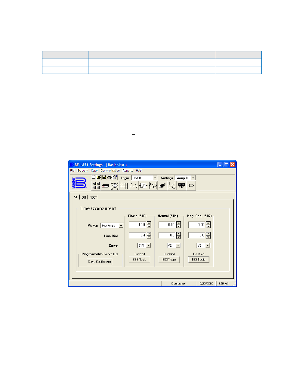
Operating Settings for Time Overcurrent Protection
Operating settings are made using BESTCOMS. Figure 4-14 illustrates the BESTCOMS screen used to
select operational settings for the time overcurrent element. To open the Overcurrent screen for Time
Overcurrent, select Overcurrent from the Screens pull-down menu and select the 51 tab. Alternately,
operating settings can be made using the S<g>-x51 (setting group number-51/151) ASCII command or
from the front panel HMI using Screens 5.x.2.1 through 5.x.2.3 where x equals 1 for Setting Group 0, 2 for
Setting Group 1, 3 for Setting Group 2, and 4 for Setting Group 3.
Figure 4-14. Overcurrent Screen, 51 Tab
At the top center of the screen is a pull-down menu labeled Logic. This menu allows viewing of the
BESTlogic settings for each preprogrammed logic scheme. User or custom logic must be selected on this
menu in order to allow changes to be made to the mode and inputs of the element. See Section 7,
BESTlogic Programmable Logic, Logic Schemes.
To the right of the Logic pull-down menu is a pull-down menu labeled Settings. The Settings menu is used
to select the setting group that the element’s settings apply to.
9289900990 Rev R
BE1-851 Protection and Control
4-15