Function block logic settings, Function block logic settings -2, Figure 2-1. 79 reclosing function block -2 – Basler Electric BE1-851 User Manual
Page 32
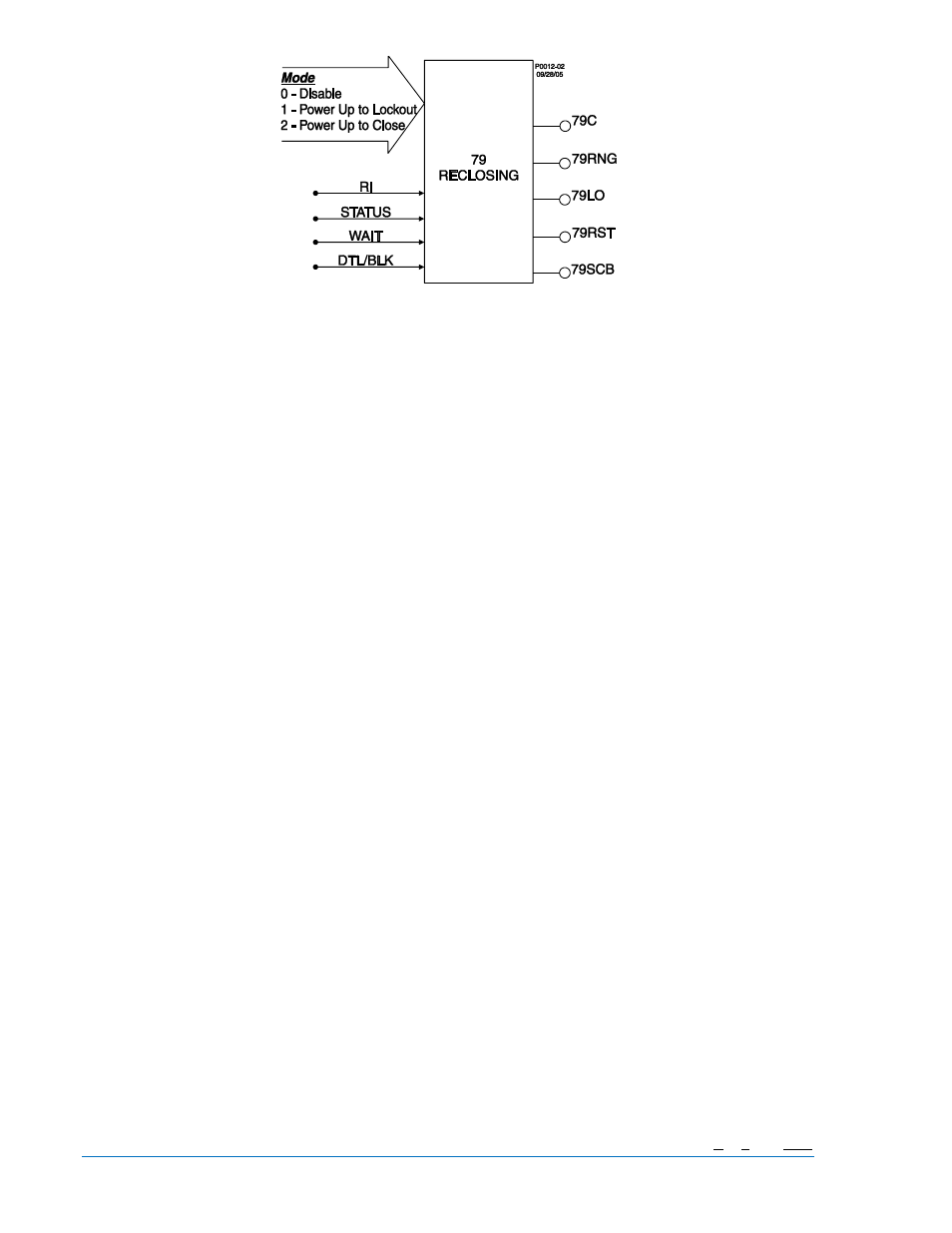
Figure 2-1. 79 Reclosing Function Block
Four inputs:
•
RI (reclose initiate)
•
STATUS (breaker position)
•
WAIT
•
DTL/BLK (drive to lockout/block 79 operation)
Five Outputs:
•
79C (close)
•
79RNG (recloser running)
•
79F (reclose fail)
•
79LO (lockout)
•
79SCB (sequence controlled block signal)
One mode setting selected from three available settings:
•
Disabled, power up to lockout mode, or power up to close mode
Eight operational settings:
•
Four reclose times (1, 2, 3, & 4)
•
Reset time
•
Reclose fail time
•
Max cycle time
•
Selected steps in the reclosing sequence that can be used to block tripping elements (same
functions as the toggle switches on the BE1-79M relay).
Of the above characteristics, the operational settings are not included in the logic settings. They are
contained in the protection settings. This is an important distinction. Since changing logic settings is
similar to rewiring a panel, the logic settings are separate and distinct from the operational settings such
as pickups and time delays.
Function Block Logic Settings
To use a protection or control function block, the two items that need to be set are mode and input logic.
The mode is equivalent to deciding which devices you want to install in your protection and control
scheme. You then must set the logic variables that will be connected to the inputs.
For example, the 51N function block has two modes (disabled and enabled) and one input, block (torque
control). To use this function block, the logic setting command might be SL-51N=1,/IN2 for Set Logic-51N
2-2
BE1-851 Quick Start
9289900990 Rev R