Alarms, Fault recording – Basler Electric BE1-851 User Manual
Page 319
Use the Breaker Duty Monitoring pull-down menu to select the operating Mode. Click in the field for 100%
Duty Maximum and set the value. Logic settings for the Block Accumulation Logic can be made by
clicking on the Logic button and with your custom logic selected, select the block accumulation logic.
Because the relay is completely programmable, it is necessary to program which logic variable monitors
breaker status (how the relay knows when the breaker is closed). Set the Breaker Status Logic by clicking
on the Logic button and with your custom logic selected, select the control logic.
Three breaker alarm points are programmable for checking breaker-monitoring functions. Each alarm
point can be programmed to monitor any of the three breaker monitoring functions or all three alarm
points can be programmed to monitor one function and alarm at various threshold levels. Use the pull-
down menu for Point 1 and select the preferred breaker-monitoring mode (function). With the Mode set,
the Threshold field is viable and has a zero threshold. Use the keyboard to enter the threshold value or
the appropriate (up or down) arrow buttons. Repeat the procedure for Breaker Alarm Points 2 and 3.
Alarms
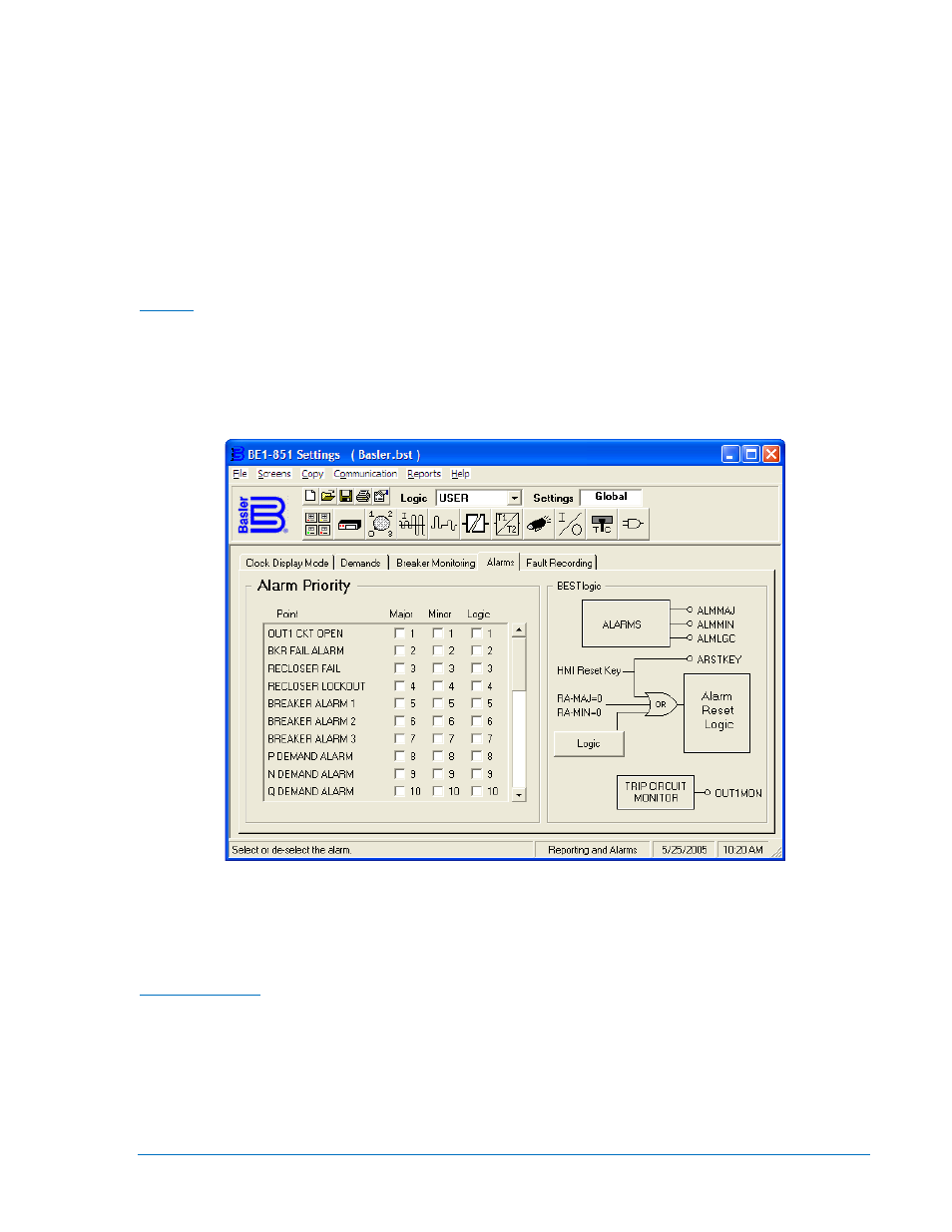
BE1-851 relays have 26 programmable alarm points. These points are for the monitored power system,
associated equipment, and non-core circuits and functions in the relay. Each of these alarm points can be
programmed to assert the Major, Minor, or Logic Alarms when an alarm point is activated. To program an
alarm point, find the point in the Alarm Priority list and then click on the appropriate field under the Major,
Minor, or Logic Alarm. See Figure 14-19.
Figure 14-19. Reporting and Alarms Screen, Alarms Tab
Logic settings for the Alarm Reset Logic can be made by clicking on the BESTlogic Logic button and then
clicking on the Reset input. Other logic blocks shown under BESTlogic on the Alarms tab are shown for
reference only. There is no interaction available.
Fault Recording
Logic expressions define the three conditions that determine when a fault has occurred. If a fault is
detected by the relay, the relay records (stores in memory) data about the fault. The three conditions that
determine a fault are Trip, Pickup, and Logic Trigger. To define these conditions, click on Fault Recording,
- Logic button and then click on Tripped, Pickup, and Logic in turn, and program the inputs that define
each condition. See Figure 14-20. You may clear the existing programming by clicking on the Clear
button or clicking on each individual variable.
9289900990 Rev R
BE1-851 BESTCOMS™ Software
14-15