Mode 4, oscillator, Mode 5, integrating timer, Mode 4, oscillator -25 – Basler Electric BE1-851 User Manual
Page 81: Mode 5, integrating timer -25, Figure 4-25. mode 4, oscillator -25, Figure 4-26. mode 5, integrating timer -25
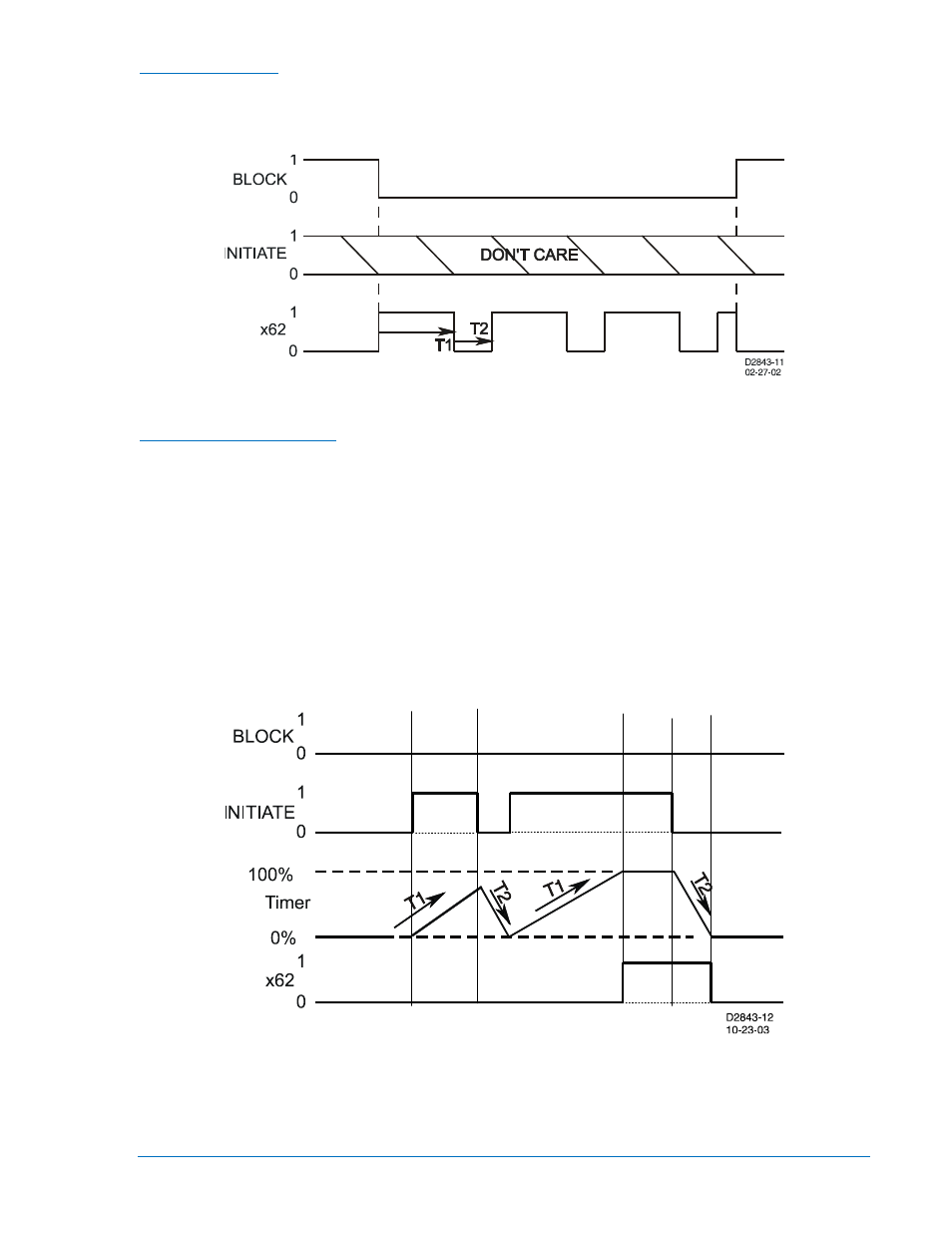
Mode 4, Oscillator
In this mode, the INITIATE input is ignored. See Figure 4-25. If the BLOCK input is FALSE, the output,
x62, oscillates with an ON time of T1 and an OFF time of T2. When the BLOCK input is held TRUE, the
oscillator stops and the output is held OFF.
Figure 4-25. Mode 4, Oscillator
Mode 5, Integrating Timer
An integrating timer is similar to a pickup/dropout timer except that the PICKUP time T1 defines the rate
that the timer integrates toward timing out and setting the output to TRUE. (See Figure 4-26.) Conversely,
the RESET time T2 defines the rate that the timer integrates toward dropout and resetting the output to
FALSE. PICKUP time T1 defines the time delay for the output to change to TRUE if the initiate input
becomes TRUE and stays TRUE. RESET time T2 defines the time delay for the output to change to
FALSE if it is presently TRUE and the initiate input becomes FALSE and stays FALSE.
In the example shown in Figure 4-26, RESET time T2 is set to half of the PICKUP time T1 setting. The
initiate input expression becomes TRUE and the timer starts integrating toward pickup. Prior to timing out,
the initiate expression toggles to FALSE and the timer starts resetting at twice the rate as it was
integrating toward time out. It stays FALSE long enough for the integrating timer to reset completely but
then toggles back to TRUE and stays TRUE for the entire duration of time T1. At that point, the output of
the timer is toggled to TRUE. Then at some time later, the initiate expression becomes FALSE and stays
FALSE for the duration of RESET time T2. At that point, the output of the timer is toggled FALSE.
Figure 4-26. Mode 5, Integrating Timer
This type of timer is useful in applications where a monitored signal may be hovering at its threshold
between on and off. For example, it is desired to take some action when current is above a certain level
for a certain period of time. A 50T function could be used to monitor the current level. Thus, if the current
level is near the threshold so that the INITIATE input toggles between TRUE and FALSE from time to
9289900990 Rev R
BE1-851 Protection and Control
4-25