Menu tree, Menu tree -2, Figure 10-2. menu tree branches -2 – Basler Electric BE1-851 User Manual
Page 232
Locator
Description
D, E
Minor Alarm and Major Alarm LEDs - When these LEDs are ON, it indicates a minor or
major alarm status. Refer to Section 6, Reporting and Alarms, for a complete description
of minor or major alarms.
F
Trip LED - When this LED is flashing ON, it indicates that a protective element is pickup
up. When this LED in ON continuously, it indicates that a trip output is closed. The LED is
sealed-in if a protective trip has occurred and there are targets being displayed.
G
Communication Port 0 - This is an RS-232 serial port. A computer terminal or PC running
BESTCOMS™ software or terminal emulation software (such as Windows® Hyper
Terminal) can be connected to this port so that the user may send commands to the relay
or receive reports from the relay. Communication with the relay uses a simple ASCII
command language.
H
Reset Pushbutton Switch - Pushing this switch resets data including sealed-in trip targets,
the Trip LED, peak demand currents, and alarms. It aborts the editing session without
saving changes.
I
Scrolling Pushbuttons - Scrolls UP/DOWN/LEFT/RIGHT through the LCD’s menu tree or
when in the Edit mode.
J
Edit Pushbutton Switch - Enable settings changes.
K
Identification Label - This ID label lists the relay’s sensing input current range, power
supply type, serial number, and style number.
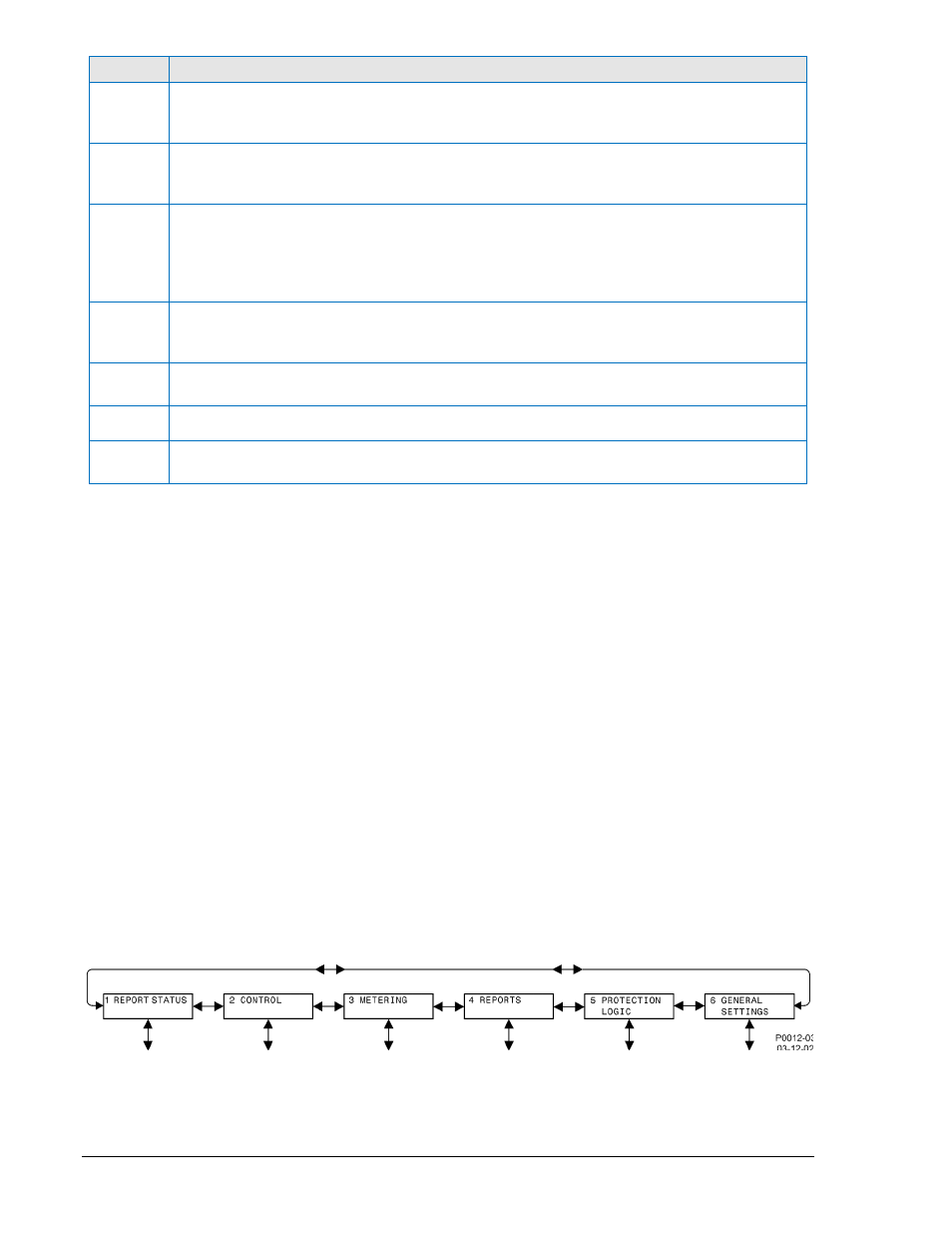
Menu Tree
The menu tree has six branches. These branches are:
1. REPORT STATUS. Display and resetting of general status information such as targets, alarms,
recloser status, etc.
2. CONTROL. Operation of control functions such as controlling virtual switches, selection of active
setting group, etc.
3. METERING. Display of real time metering values.
4. REPORTS. Display and resetting of report information such as time and date, demand registers,
breaker duty statistics, etc.
5. PROTECTION LOGIC. Display and setting of protective function setting parameters such as
pickups, time delays, etc.
6. GENERAL SETTINGS. Display and setting of non-protective function setting parameters such as
communication, CT ratios, connections, etc.
Each screen in the menu tree is numbered in the upper left hand corner of the screen. This number
indicates the current branch and level in the menu tree structure so that you do not loose track of where
you are when you have left the top level of the menu tree. You scroll through each level of the menu tree
by using the RIGHT and LEFT scrolling keys. To go to a level of detail, you use the DOWN scrolling key.
Each time you go to a lower level in the menu tree, another number is added to the screen number
separated by a period. Figures 10-2 through 10-8 illustrate all branches in the menu tree.
Figure 10-2. Menu Tree Branches
10-2
BE1-851 Human-Machine Interface
9289900990 Rev R