51 - time overcurrent protection, 51 - time overcurrent protection -13, Figure 4-12. time overcurrent logic block -13 – Basler Electric BE1-851 User Manual
Page 69
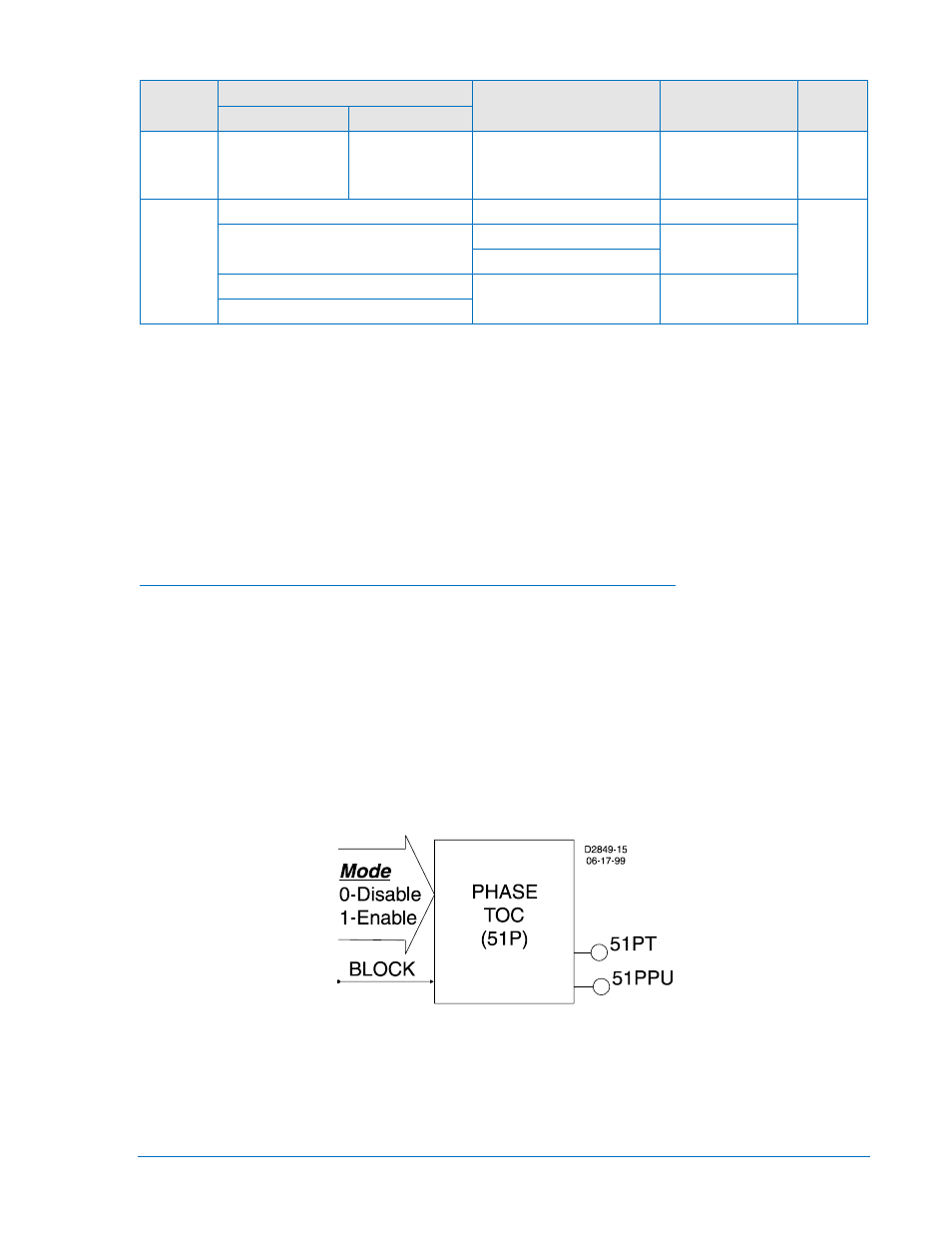
Table 4-5. Operating Settings for Instantaneous Overcurrent Protection
Setting
Range
Increment
Unit of Measure Default
1 A
5 A
Pickup
0 = Disabled
0.1 to 30
0 = Disabled
0.5 to 150
0.01 for 0.1 to 9.99
0.1 for 10.0 to 99.9
1.0 for 100 to 150
Secondary Amps
0
Time
0 to 999 milliseconds
1
Milliseconds
0
0.1 to 60 seconds
0.1 for 0.1 to 9.9
Seconds
1.0 for 10 to 60
0 to 3600 cycles (60 Hz)
∗
Cycles
0 to 2500 cycles (50 Hz)
∗
Time delays less than 10 cycles can be entered to the nearest 0.1 cycles from the HMI. All time delays
can be entered to the nearest 0.01 cycles from the ASCII command interface. Time delays entered in
cycles are converted to milliseconds or seconds. Increment precision after conversion is limited to that
appropriate for each of those units of measure.
Example 1. Make the following operating settings to the 50TP element. Refer to Figure 4-11.
Logic:
User
Settings:
Setting Group 0
Pickup:
25 secondary amps
Time:
10 seconds
Retrieving Instantaneous Overcurrent Protection Status from the Relay
The status of each logic variable can be determined through the ASCII command interface using the RG-
STAT (report general-status) command. It cannot be determined using BESTCOMS. See Section 6,
Reporting and Alarms, General Status Reporting, for more information.
51 - Time Overcurrent Protection
Sensing input type H relays have one function block for phase (51P), one for neutral (51N), and one for
negative-sequence (51Q) inverse time overcurrent protection. Sensing input type G relays have one
function block for phase (51P) and two for neutral (51N, 151N).
Each of the four independent function blocks has two logic outputs, pickup, and trip. A T at the end of its
label indicates the trip output and a PU indicates pickup. The first letter of the label indicates the element
type where P is a phase element, N is a neutral element, and Q is a negative-sequence element. The 51
element illustrated in Figure 4-12 is a phase element.
Figure 4-12. Time Overcurrent Logic Block
A Block logic input is provided to each function block that can be used to disable the function. When this
expression is true, forcing the outputs to logic zero and resetting the timers to zero disable the function.
For example, this could be used similar to a torque control contact on an electro-mechanical relay.
Each inverse time overcurrent function has a Pickup, a Time Dial, and a Curve setting. See Appendix A,
Time Overcurrent Characteristic Curves, for details on each of the curves available. To make the
protective element use integrated reset and emulate an electro-mechanical induction disk reset
9289900990 Rev R
BE1-851 Protection and Control
4-13