General, Section 13 • testing and maintenance -1, General -1 – Basler Electric BE1-851 User Manual
Page 289: Figure 13-1. terminals and connections -1
Advertising
SECTION 13 • TESTING AND MAINTENANCE
General
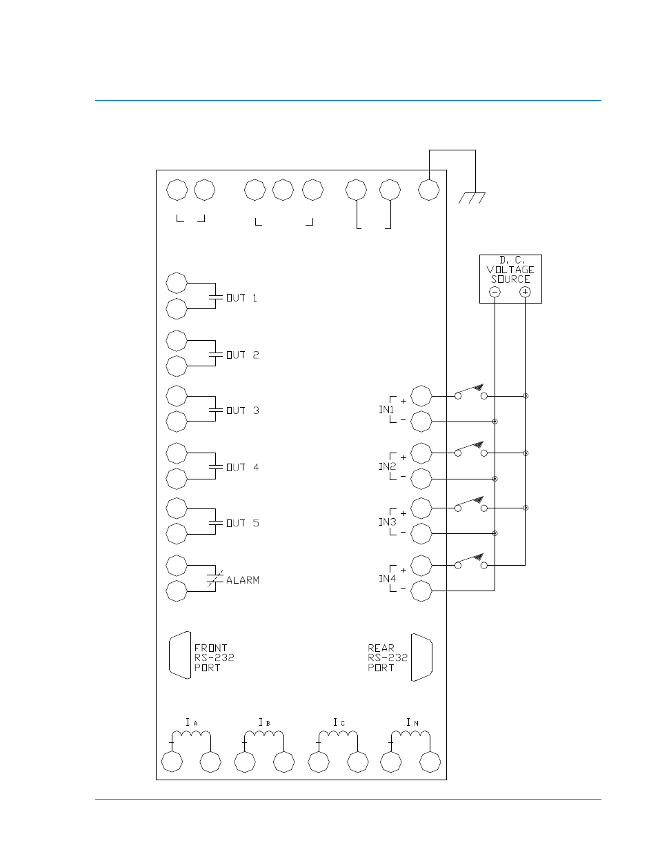
You may prefer to test your relay before installation. To verify functionality of the BE1-851 relay, perform
the procedures provided in the following paragraphs. A relay terminals and connections diagram is
provided in Figure 13-1.
Figure 13-1. Terminals and Connections
A1
A2
A3
A4
A5
A6
A7
A8
C1
C2
C3
C4
C5
C6
C7
C8
C9
C10
C11
C12
D1
D2
D3
D4
D5
D6
D7
D8
B7
B8
B4
B5
B6
B2
B3
B1
+
-
A
B
C
IRIG
RS-485
PWR
INPUT
CHAS.
GND
D2518-03
03-10-06
9289900990 Rev R
BE1-851 Testing and Maintenance
13-1
Advertising
This manual is related to the following products: