Mode 6, latch, Mode 6, latch -26, Figure 4-27. mode 6, latch -26 – Basler Electric BE1-851 User Manual
Page 82
time, the function will still time out as long as the time that it is TRUE is longer than the time that it is
FALSE. With a simple pickup/dropout timer, the timing function would reset to zero and start over each
time the initiate expression became FALSE.
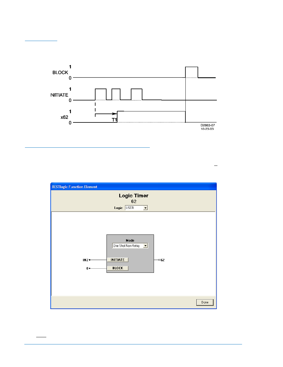
Mode 6, Latch
A one-shot timer starts its timing sequence when the INITIATE input expression changes from FALSE to
TRUE. See Figure 4-27. The timer will time for DELAY time T1 and then the output will latch TRUE.
Additional INITIATE input expression changes of state are ignored. Time (T2) is ignored.
Figure 4-27. Mode 6, Latch
BESTlogic™ Settings for General Purpose Logic Timers
BESTlogic settings are made from the BESTlogic Function Element screen in BESTCOMS. Figure 4-28
illustrates the BESTCOMS screen used to select BESTlogic settings for the Logic Timer elements. To
open the BESTlogic Function Element screen for Logic Timer, select Logic Timers from the Screens pull-
down menu. Then select the BESTlogic button for either the 62 or the 162 element. Alternately, settings
may be made using the SL-x62 ASCII command.
Figure 4-28. BESTlogic Function Element Screen, 62
At the top center of the BESTlogic Function Element screen is a pull-down menu labeled Logic. This
menu allows viewing of the BESTlogic settings for each preprogrammed logic scheme. User or custom
logic must be selected on this menu in order to allow changes to the mode and inputs of the element.
Enable the Logic Timer function by selecting its mode of operation from the Mode pull-down menu.
4-26
BE1-851 Protection and Control
9289900990 Rev R