HEIDENHAIN IK 5494-2D User Manual
Page 112
Advertising
90
QC5200 Series User’s Guide
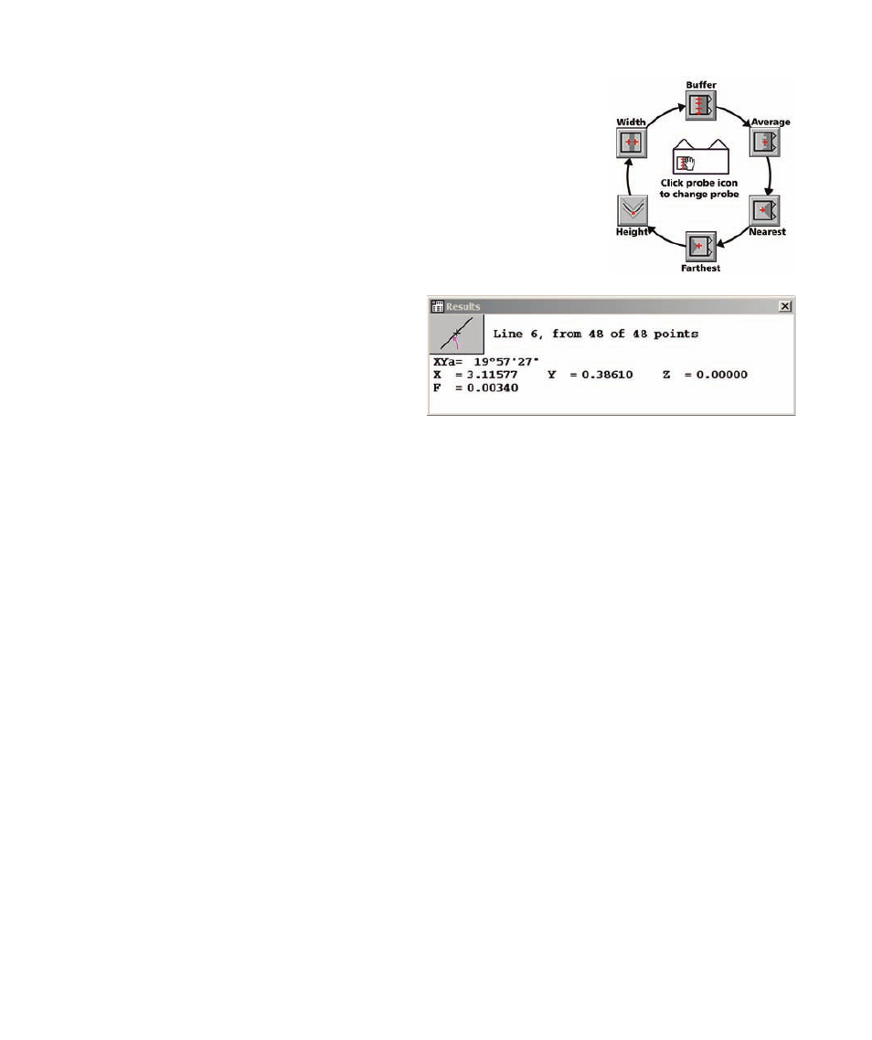
The buffer probe can be obtained from a collection of six probes by clicking
on the probe icon. Repeatedly clicking the probe icon cycles through the six
probes shown here in this diagram.
Measurement results are sent to the Features tem-
plate and the Results window. The results data
for line measurements include:
• The feature type and feature number
• The number of points acquired and the
number of points used to calculate feature data
• The angle created between the line and the X-axis. Angles become more positive as they
rotate counterclockwise.
• The geometric center location of the feature
• The form value
Advertising