Conducting profile measurements, Profile measurements – HEIDENHAIN IK 5494-2D User Manual
Page 181
5
Measuring
159
Conducting profile measurements
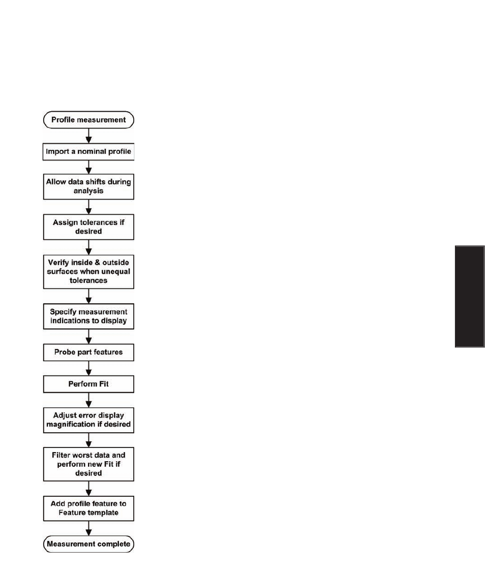
This diagram outlines the steps required to perform a typical profile measurement. The details of each step
are described in the profile measurement instructions that follow. Details regarding the use of tools found
in the profile window, menu and toolbar are discussed after the profile measurement instructions.
Profiles can be imported from .dxf or .igs drawing files, or from the Features
template
Probed and imported data can be shifted in the X and Y axes, and can be rotated
during the Fit operation to maximize the fit of probed data to the nominal profile
Equal and unequal bilateral tolerances can be assigned to the measurement
Inside and outside material surfaces can be specified manually for the imported data
to insure conformance with the nominal profile
Any of the seven measurement indications can be displayed or hidden
Probe the part features using crosshairs or optical edge detecion
The probed feature data is matched to the nominal part profile
The differences between the nominal part profile and the probed data are displayed
as error whiskers that can be displayed at different magnifications
Probing errors can be individually filtered out of measurement results in preparation
for a revised Fit operation
The completed profile mesurement results are added to the feature template, shown
in the Part View window and shown in the Results window
Profile Measurements