Allowing crosshair probe rotation – HEIDENHAIN IK 5494-2D User Manual
Page 366
344
QC5200 Series User’s Guide
Step 4
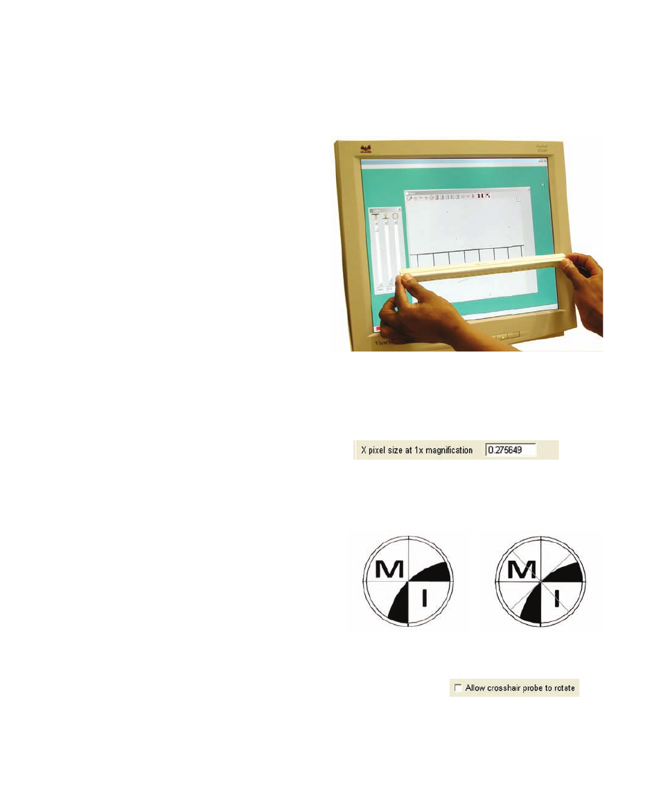
Bring a standard artifact into sharp focus in the video Window’s field of view. The Metronics calibration
slide is an excellent standard to use for this procedure.
Step 5
Measure the distance between 2 of the standard’s
marks on the computer screen using a scale or ruler.
Measure as great a distance as possible.
Step 6
Calculate the measured magnification by dividing
the measured distance (Step 5) by the actual dis-
tance shown on the standard.
Measured magnification = Measured / Actual
Step 7
Calculate the pixel size factor by dividing the mea-
sured magnification by the magnification value currently displayed in the right corner of the status bar.
Pixel size factor = Measured Magnification / Status bar value
Step 8
Enter the pixel size factor into the X pixel size... field.
Allowing crosshair probe rotation
Probes that detect edges are most effective when ori-
ented orthogonally to the edge. Since feature edges
can be positioned at any angle, edge detection probe
rotation is enabled by default. However, crosshair
probes are point measurement tools and probe rota-
tion is disabled by default. Crosshair probe rotation
can be useful when the feature geometry makes the
crosshairs difficult to see on the screen.
Check the Allow crosshair probe to rotate box to enable crosshair rotation.
Rotated crosshairs are easier to see against some
backgrounds