HEIDENHAIN IK 5494-2D User Manual
Page 299
Advertising
277
8
Programming
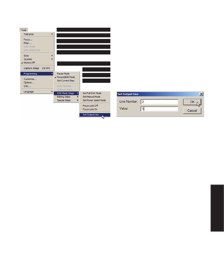
Setting output lines
Two pins of the QC5200 axis board I/O connector and eight pins of the zoom I/O
connector can be set to logic 0 or a logic 1 levels. This function is used in conjunc-
tion with hardware configurations created by the system distributor or OEM, so no
specific pinout or logic level information can be provided here. Consult your system
supplier for details regarding pinouts and logic levels.
To set an output line, click the Tools/Programming/CNC Mode Steps/Set Output Line
function. The Set Output Line dialog box will be displayed. Consult
your system I/O connection documentation and enter the line number
and logic level value (1 or 0) into the fields provided.
Editing Programs
Advertising