Probing and measuring features – HEIDENHAIN IK 5494-2D User Manual
Page 169
5
Measuring
147
Lines
A minimum of two probed points is required
to measure a line. There is no practical limit to
the number of points that can be probed, and in
general accuracy is increased by probing more
points.
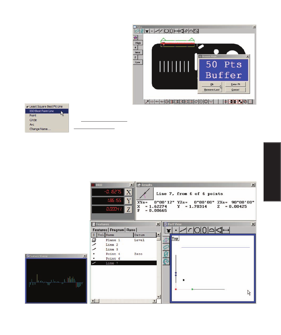
A best-fit algorithm is used to define the line
when more than two points are probed. The line
fit to the probed data can easily be changed by
right-clicking the Results window and select-
ing the desired fitting
algorithm. Please refer
to Appendix C: Data
Appendix C: Data
Fitting Algorithms
Fitting Algorithms for details regarding the fitting algorithms.
Measurement results are shown in the Features template, Part View window and Results window. The
Results window shows the feature identification number, the number of points used in the measurement,
the angular orientation of the line, the coordinate location of the center of the line and the form error. When
only the two required points are probed, the form error is zero. When more than two points are probed, the
form error is the sum of the two greatest opposing error magnitudes.
Click the feature stamp
icon in the left corner of the
Results window to display
the Feature Stamp window.
The line will be shown
with data point form er-
rors in blue, filtered points
in yellow and the greatest
two opposing form errors
in red.
Fifty points are probed using the Buffer probe to measure
a line feature
Probing and Measuring Features