Example configurations, Transmitter logic, Example configurations -2 – Altera Embedded Peripherals IP User Manual
Page 108: Transmitter logic -2, Figure 10-1: spi core block diagram (master mode)
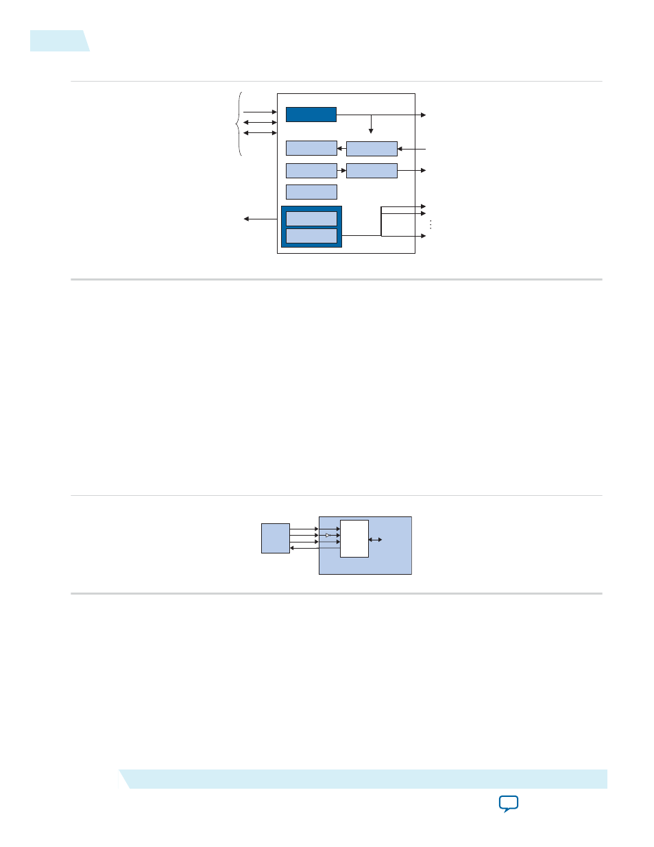
Figure 10-1: SPI Core Block Diagram (Master Mode)
clock
control
control
baud rate divisor*
IRQ
sclk
mosi
miso
ss_n0
ss_n1
ss_n15
*Not present on SPI sl
ave
slaveselect*
Avalon-MM
slave
interface
to on-chip
logic
txdata
shift register
status
rxdata
shift register
data
The SPI core logic is synchronous to the clock input provided by the Avalon-MM interface. When
configured as a master, the core divides the Avalon-MM clock to generate the SCLK output. When
configured as a slave, the core's receive logic is synchronized to SCLK input. The core's Avalon-MM
interface is capable of Avalon-MM transfers with flow control. The SPI core can be used in conjunction
with a DMA controller with flow control to automate continuous data transfers between, for example, the
SPI core and memory.
For more details, refer to
Interval Timer Core
.
Example Configurations
The SPI Core block diagram and the SPI Core Configured as a Slave diagram show two possible
configurations. In below in the SPI Core Configured as a Slave diagram, the SPI core provides a slave
interface to an off-chip SPI master.
Figure 10-2: SPI Core Configured as a Slave
Altera FPGA
Avalon-MM
interface
to on-chip
logic
sclk
ss_n
mosi
miso
SPI component
(configured as sl
ave)
miso
mosi
ss
sclk
SPI
Master
Device
In the SPI Core Block Diagram, the SPI core provides a master interface driving multiple off-chip slave
devices. Each slave device in the SPI Core Configured as a Slave figure must tristate its
miso
output
whenever its select signal is not asserted.
The
ss_n
signal is active-low. However, any signal can be inverted inside the FPGA, allowing the slave-
select signals to be either active high or active low.
Transmitter Logic
The SPI core transmitter logic consists of a transmit holding register (
txdata
) and transmit shift register,
each n bits wide. The register width n is specified at system generation time, and can be any integer value
10-2
Example Configurations
UG-01085
2014.24.07
Altera Corporation
SPI Core