Altera Embedded Peripherals IP User Manual
Page 255
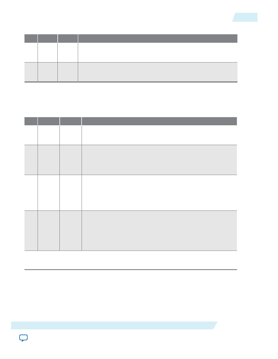
Table 25-5: status Register Bits
Bit
Name
R/W/C
Description
0
TO
RC
The
TO
(timeout) bit is set to 1 when the internal counter reaches zero.
Once set by a timeout event, the
TO
bit stays set until explicitly cleared by a
master peripheral. Write zero to the
status
register to clear the
TO
bit.
1
RUN
R
The
RUN
bit reads as 1 when the internal counter is running; otherwise this
bit reads as 0. The
RUN
bit is not changed by a write operation to the
status
register.
control Register
The
control
register has four defined bits.
Table 25-6: control Register Bits
Bit
Name
R/W/C
Description
0
ITO
RW
If the
ITO
bit is 1, the interval timer core generates an IRQ when the
status
register’s
TO
bit is 1. When the
ITO
bit is 0, the timer does not
generate IRQs.
1
CONT
RW
The
CONT
(continuous) bit determines how the internal counter behaves
when it reaches zero. If the
CONT
bit is 1, the counter runs continuously
until it is stopped by the
STOP
bit. If
CONT
is 0, the counter stops after it
reaches zero. When the counter reaches zero, it reloads with the value
stored in the period registers, regardless of the
CONT
bit.
2
START
W
Writing a 1 to the
START
bit starts the internal counter running
(counting down). The
START
bit is an event bit that enables the counter
when a write operation is performed. If the timer is stopped, writing a 1
to the
START
bit causes the timer to restart counting from the number
currently stored in its counter. If the timer is already running, writing a
1 to
START
has no effect. Writing 0 to the
START
bit has no effect.
3 STOP
W
Writing a 1 to the
STOP
bit stops the internal counter. The
STOP
bit is an
event bit that causes the counter to stop when a write operation is
performed. If the timer is already stopped, writing a 1 to
STOP
has no
effect. Writing a 0 to the stop bit has no effect.
If the timer hardware is configured with Start/Stop control bits off,
writing the
STOP
bit has no effect.
1. Writing 1 to both
START
and
STOP
bits simultaneously produces an undefined result.
UG-01085
2014.24.07
Register Map
25-7
Interval Timer Core
Altera Corporation