Clock and baud rate selection, Software programming model, Overview – Altera Embedded Peripherals IP User Manual
Page 96: Supported features, Clock and baud rate selection -10, Software programming model -10, Overview -10, Supported features -10
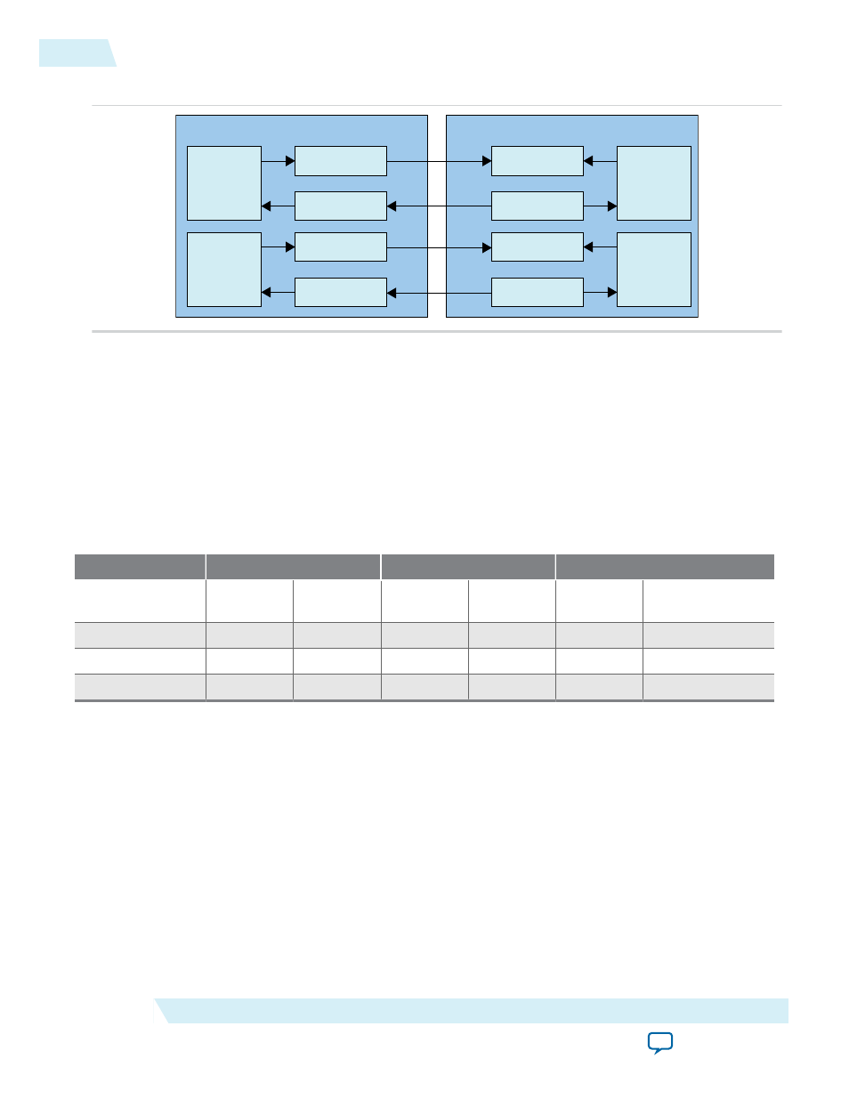
Figure 9-5: Hardware Auto Flow-Control Between two UARTs
TX
FIFO
Transmit Buffer
Flow Control
RX
FIFO
Receive Buffer
Flow Control
RX
FIFO
Receive Buffer
Flow Control
TX
FIFO
Transmit Buffer
Flow Control
sout
cts_n
sin
rts_n
sin
rts_n
sout
cts_n
UART 1
UART 2
Clock and Baud Rate Selection
The Soft-UART supports only one clock. The same clock is used on the Avalon-MM interface and will be
used to generate the baud clock that drives the serial UART interface.
The baud rate on the serial UART interface is set using the following equation:
Baud Rate = Clock/(16 x Divisor)
The table below shows how several typical baud rates can be achieved by programming the divisor values
in Divisor Latch High and Divisor Latch Low register.
Table 9-11: UART Clock Frequency, Divider value and Baud Rate Relationship
18.432 MHz
24 MHz
50 MHz
Baud Rate
Divisor for
16x clock
% Error
(baud)
Divisor for
16x clock
% Error
(baud)
Divisor for
16x clock
% Error (baud)
9,600
120
0.00%
156
0.16%
326
-0.15%
38,400
30
0.00%
39
0.16%
81
0.47%
115,200
10
0.00%
13
0.16%
27
0.47%
Software Programming Model
Overview
The following describes the programming model for the Altera compatible16550.
Supported Features
For the following features, the 16550 Soft-UART HAL driver can be configurable in run time or generate
time. For run-time configuration, users can use “altera_16550_uart_config” API . Generate time is during
9-10
Clock and Baud Rate Selection
UG-01085
2014.24.07
Altera Corporation
16550 UART