Functional description, Pci-avalon bridge blocks, Functional description -2 – Altera Embedded Peripherals IP User Manual
Page 136: Pci-avalon bridge blocks -2, Aluts
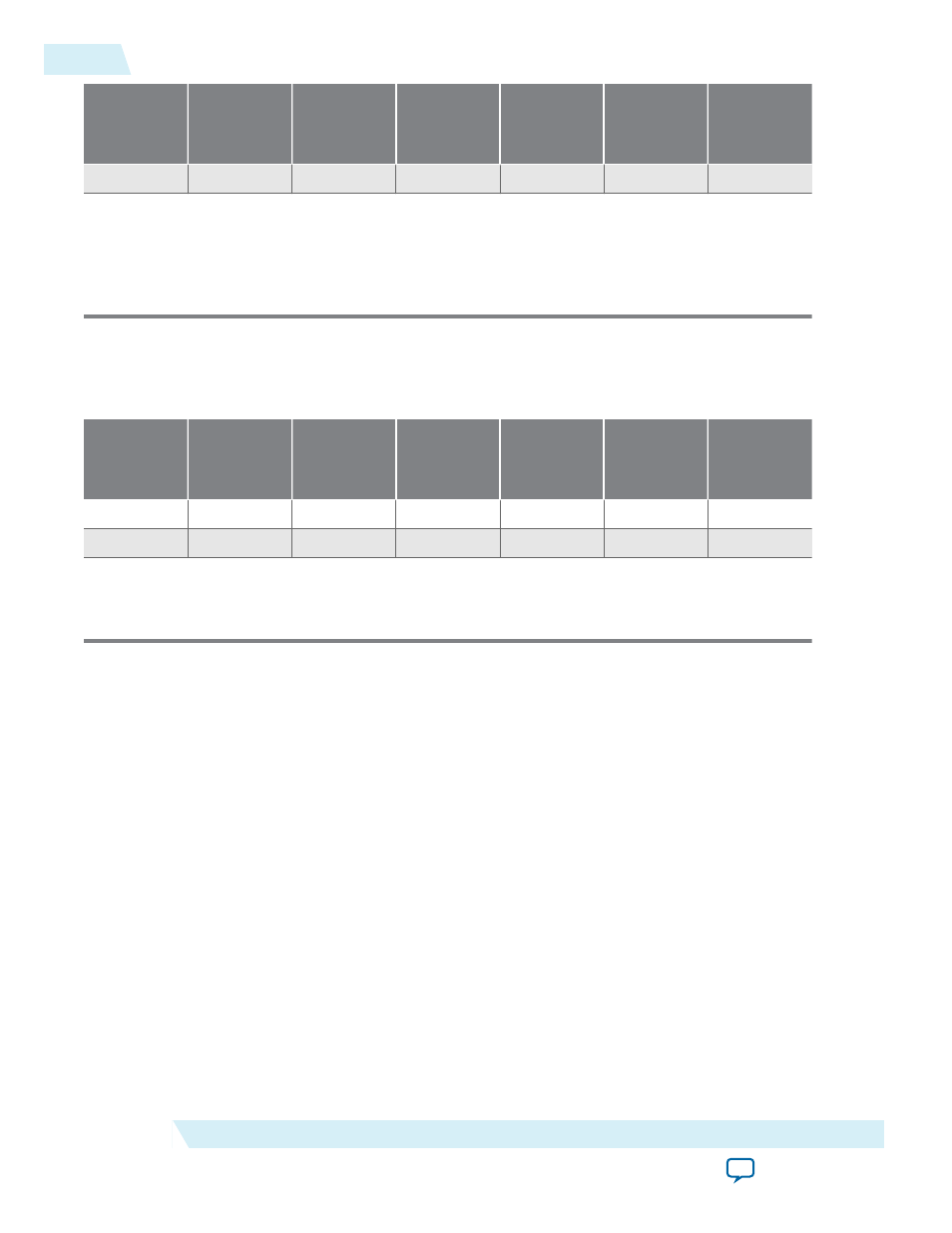
PCI
Device
Mode
PCI Target
PCI Master
Logic
Register
M9K Memory
Blocks
I/O Pins
Enabled
Enabled
1,347
876
5
50
1. Min = One BAR with minimum settings for each parameter.
Max = Three BARs with maximum settings for each parameter.
2. The logic element (LE) count for the Stratix III family is based on the number of adaptive
look-up tables (ALUTs) used for the design as reported by the Quartus II software.
Below the table lists the resource utilization and performance data for a Cyclone III device
(EP3C40F780C6).
Table 14-2: Memory Utilization and Performance Data for the Cyclone III Family
PCI
Device
Mode
PCI Target
PCI Master
Logic
Elements
Logic
Register
M4K Memory
Blocks
I/O Pins
Enabled
N/A
1,057
511
2
48
Enabled
Enabled
2,027
878
5
50
1. Min = One BAR with minimum settings for each parameter.
Max = Three BARs with maximum settings for each parameter.
Functional Description
The following sections provide a functional description of the PCI Lite Core.
PCI-Avalon Bridge Blocks
The PCI-Avalon bridge's blocks manage the connectivity for the following PCI operational modes:
• PCI Target-Only Peripheral
• PCI Master/Target Peripheral
• PCI Host-Bridge Device
Depending on the operational mode, the PCI-Avalon bridge uses some or all of the predefined Avalon-
MM ports. The Generic PCI Avalon Bride Block Diagram shows a generic PCI-Avalon bridge block
diagram, which includes the following blocks:
• Five predefined Avalon-MM ports
• Control registers
• PCI master controller (when applicable)
• PCI target controller
14-2
Functional Description
UG-01085
2014.24.07
Altera Corporation
PCI Lite Core