Altera Embedded Peripherals IP User Manual
Page 196
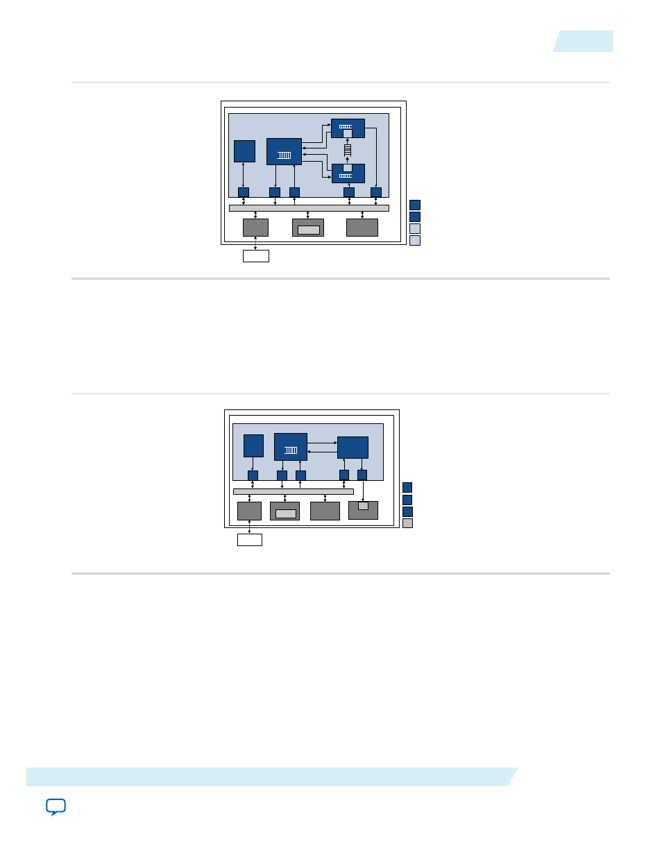
Figure 21-3: Example of Memory-to-Memory Configuration
M
Ava lo n -MM Ma s te r P o rt
S
Avalo n- MM S la ve P o rt
Avalo n- S T S o ur c e P or t
S RC
Av a lon -S T S in k P o rt
S NK
S O PC Build er S ys te m
Alte ra F PG A
De s c rip to r
P ro c e ss o r
B lo c k
S ca tte r G a th er DMA C on tro lle r C o re
R d
S
M
Wr
c o m m an d
st a tu s
M
M
c o m m a n d
st a tu s
M
Con tro l
&
S ta tu s
Re g ist e rs
DMA Write B lo c k
SN K
DMA Re ad B lo c k
SR C
Da ta
FIFO
Nio s II
P ro c es s o r
DD R 2
SDRA M
Me m o ry
Con tro lle r
S ys te m In te rc on ne c t F a b ric
Me m o ry
De s c riptor
Ta b le
Memory-to-Stream Configuration
Memory-to-stream configurations include the descriptor processor and DMA read blocks.
In this example, the Nios II processor and descriptor table are in the FPGA. Data from an external DDR2
SDRAM is read by the SG-DMA controller and written to an on-chip streaming peripheral.
Figure 21-4: Example of Memory-to-Stream Configuration
SN K
M
Ava lon-MM Ma s ter P ort
S
Ava lon-MM S la ve P ort
Ava lon-ST S ource P ort
Ava lon-S T Sink P ort
S OPC Builder S yste m
Altera FP GA
Sc a tte r Gat her DMA Controlle r Core
Rd
S
M
Wr
M
M
c o mm and
s tatu s
SR C
Contro l
&
S tatus
Regis ters
Nio s II
Pro c e ss o r
DDR2
SDR AM
Me mory
Contr o lle r
Me mo ry
De s criptor
Tab le
DMA Rea d Blo c k
Descr ipto r
Processo r
Blo c k
SR C
S trea ming
Co mponent
SN K
S ys te m Inter connec t Fab ric
Stream-to-Memory Configuration
Stream-to-memory configurations include the descriptor processor and DMA write blocks. This configu‐
ration is similar to the memory-to-stream configuration as the figure below illustrates.
UG-01085
2014.24.07
Functional Blocks and Configurations
21-5
Scatter-Gather DMA Controller Core
Altera Corporation