Altera smbus core interface, Altera smbus core interface -5 – Altera Embedded Peripherals IP User Manual
Page 324
Altera SMBus Core Interface
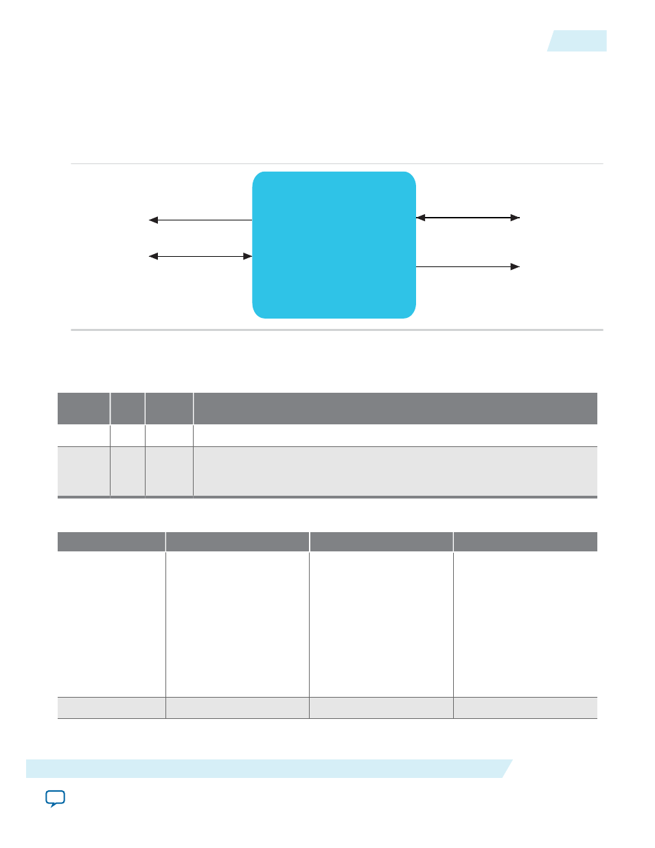
This diagram depicts the top level interfaces for the Altera SMBus Core.
Figure 33-2: Altera SMBus Core Top Level Interfaces
Altera SMBus
Core
Clock & Reset
Avalon-MM
Slave Interface
Serial Interface
Interface
The following table details the interfaces of the Altera SMBus Core.
Table 33-5: Clock and Reset
Signal
Widt
h
Directio
n
Description
clk
1
Input
System clock source used to clock the entire peripheral.
rst_n
1
Input
System asynchronous reset source used to reset the entire peripheral. This signal
is asynchronously asserted and synchronously de-asserted. The synchronous de-
assertion must be provided external to this peripheral.
Table 33-6: Avalon-MM Slave Interface
Signal
Width
Direction
Description
addr
4
Input
Avalon-MM address
The address is in units of
words. For example, 0x0
addresses the first word
of altera_smb's memory
space and 0x1 addresses
the second word of
altera_smb's memory
space.
read
1
Input
Avalon-MM read control
UG-01085
2014.24.07
Altera SMBus Core Interface
33-5
Altera MSI to GIC Generator
Altera Corporation