Addressing and address incrementing, Parameters, Dma parameters (basic) – Altera Embedded Peripherals IP User Manual
Page 234: Addressing and address incrementing -3, Parameters -3, Dma parameters (basic) -3
length registered is programmed with 64 and the burst count port will be 16. If a 64-bit data width DMA
is programmed for a doubleword transfer of 8 bytes, the length register is programmed with 8 and the
burst count port will be 1.
There is a shallow FIFO buffer between the master read and write ports. The default depth is 2, which
makes the write action depend on the data-available status of the FIFO, rather than on the status of the
master read port.
Both the read and write master ports can perform Avalon transfers with flow control, which allows the
slave peripheral to control the flow of data and terminate the DMA transaction.
For details about flow control in Avalon-MM data transfers and Avalon-MM peripherals, refer to
Addressing and Address Incrementing
When accessing memory, the read (or write) address increments by 1, 2, 4, 8, or 16 after each access,
depending on the width of the data. On the other hand, a typical peripheral device (such as UART) has
fixed register locations. In this case, the read/write address is held constant throughout the DMA
transaction.
The rules for address incrementing are, in order of priority:
• If the
control
register’s
RCON
(or
WCON
) bit is set, the read (or write) increment value is 0.
• Otherwise, the read and write increment values are set according to the transfer size specified in the
control register, as shown below.
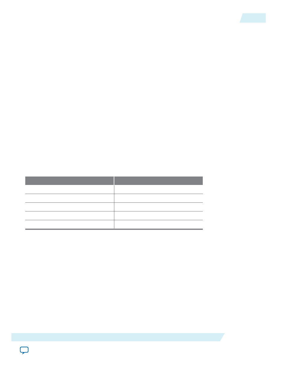
Table 23-1: Address Increment Values
Transfer Width
Increment
byte
1
halfword
2
word
4
doubleword
8
quadword
16
In systems with heterogeneous data widths, care must be taken to present the correct address or offset
when configuring the DMA to access native-aligned slaves. For example, in a system using a 32-bit
Nios II processor and a 16-bit DMA, the base address for the UART
txdata
register must be divided
by the dma_data_width/cpu_data_width—2 in this example.
Parameters
This section describes the parameters you can configure.
DMA Parameters (Basic)
The DMA Parameters page includes the following parameters.
UG-01085
2014.24.07
Addressing and Address Incrementing
23-3
DMA Controller Core
Altera Corporation