Register maps, Register maps -6 – Altera Embedded Peripherals IP User Manual
Page 275
Daisy Chaining VIC Cores
You can create a system with more than 32 interrupts by daisy chaining multiple VIC cores together. This
is done by connecting the
interrupt_controller_out
interface of one VIC to the optional
interrupt_controller_in
interface of another VIC. For information about enabling the optional input
interface, refer to the Parameters section.
For performance reasons, always directly connect VIC components. Do not include other components
between VICs.
When daisy chain input comes into the VIC, the priority processing block considers the daisy chain input
along with the hardware and software interrupt inputs from the interrupt request block to determine the
highest priority interrupt. If the daisy chain input has the highest RIL value, then the vector generation
block passes the daisy chain port values unchanged directly out of the VIC.
You can daisy chain VICs with fewer than 32 interrupt ports. The number of daisy chain connections is
only limited to the hardware and software resources. Refer to the Latency Information section for details
about the impact of multiple VICs.
Altera recommends setting the RIL width to the same value in all daisy-chained VIC components. If your
RIL widths are different, wider RILs from upstream VICs are truncated.
Latency Information
The latency of an interrupt request traveling through the VIC is the sum of the delay through each of the
blocks. Clock delays in the interrupt request block and the vector generation block are constants. The
clock delay in the priority processing block varies depending on the total number of interrupt ports.
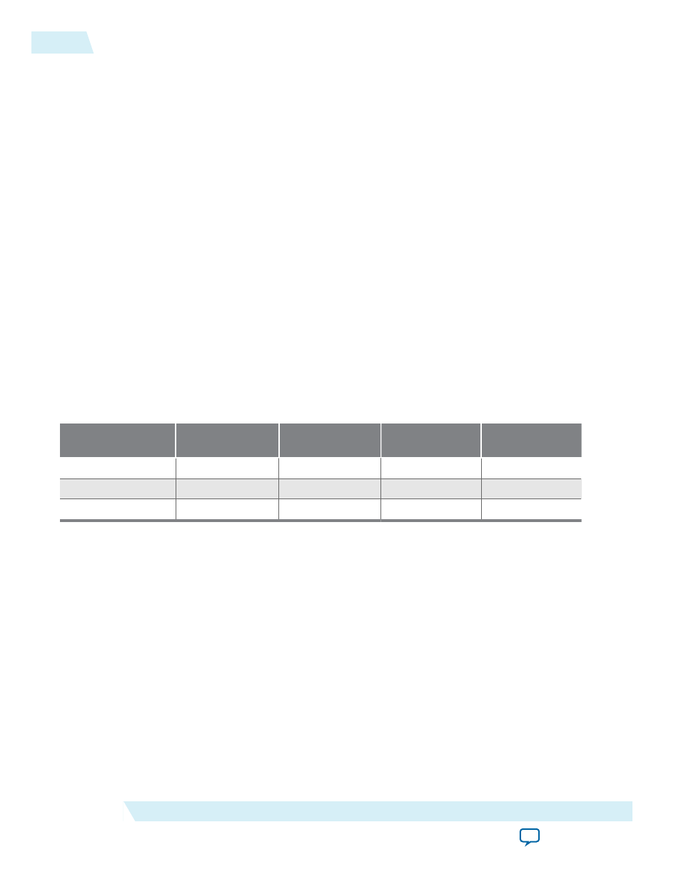
Table 28-5: Clock Delay Latencies
Number of Interrupt
Ports
Interrupt Request
Block Delay
Priority Processing
Block Delay
Vector Generation
Block Delay
Total Interrupt
Latency
2 – 4
2 cycles
1 cycle
1 cycle
4 cycles
5 – 16
2 cycles
2 cycles
1 cycle
5 cycles
17 – 32
2 cycles
3 cycles
1 cycle
6 cycles
When daisy-chaining multiple VICs, interrupt latency increases as you move through the daisy chain
away from the processor. For best performance, assign interrupts with the lowest latency requirements to
the VIC connected directly to the processor.
Register Maps
The VIC core CSRs are accessible through the Avalon-MM interface. Software can configure the core and
determine current status by accessing the registers.
Each register has a 32-bit interface that is not byte-enabled. You must access these registers with a master
that is at least 32 bits wide.
28-6
Register Maps
UG-01085
2014.24.07
Altera Corporation
Vectored Interrupt Controller Core