Fig. 13.1 – Westermo RedFox Series User Manual
Page 270
Westermo OS Management Guide
Version 4.17.0-0
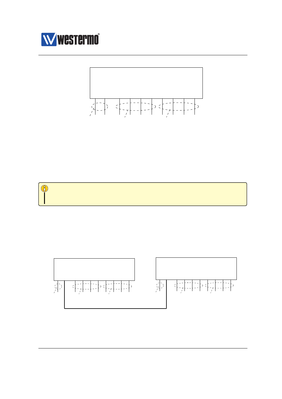
VLAN 1
ADMIN
VLAN2
OFFICE
VLAN3
MARKETING
1/1 1/2
2/1 2/2
2/3
2/4
2/5
2/6
2/7
2/8
Switch
Figure 13.1: VLANs sharing a single switch.
In this example we have assumed that only regular hosts (PCs, servers, etc.;
not other switches) attach to the ports of the switch. Traffic sent and received
on each switch port are regular Ethernet packets (without VLAN headers), and
here we refer to this by saying that the switch ports are associated with their
respective VLAN untagged.
Note
A port associated untagged on a VLAN, will send and receive regular Ether-
net packets (i.e., without VLAN header) on that port.
Consider the case where a PC attached to port 2/1 of the switch in
transmits a broadcast packet. That packet will be forwarded onto all other ports
of VLAN 2 (OFFICE), i.e., ports 2/2-2/4, but not to any of the other ports.
shows a situation where three networks, the ADMIN VLAN, the OFFICE
VLAN, and the MARKETING VLAN share two switches as well as the connection
between them.
VLAN 1
ADMIN
VLAN2
OFFICE
VLAN3
MARKETING
VLAN 1
ADMIN
VLAN2
OFFICE
VLAN3
MARKETING
1/1 1/2
2/1 2/2
2/3
2/4
2/5
2/6
2/7
2/8
Switch A
1/1 1/2
2/1 2/2
2/3
2/4
2/5
2/6
2/7
2/8
Switch B
Figure 13.2: VLANs sharing two switches and the connection between them.
270
➞ 2015 Westermo Teleindustri AB