6 tally lights, 1 external connections, Tally lights – NewTek TriCaster 300 User Manual
Page 41: External connections
Page | 25
Simply connect the secondary device to the unused video output connector (DVI or VGA) on
TriCaster’s backplane before powering up. The new device should be recognized and enabled by
the system automatically, and you can configure it using settings in TriCaster’s Live Desktop
(after creating a session).
3.6 TALLY LIGHTS
TriCaster’s Tally Light support includes Program and Preview row selections (and both). The
current Program row selection is indicated by a red LED. The Preview row selection is indicated
by a green LED. When an input is selected for both Program and Preview, the tally light will be
amber. For Virtual Inputs, the LED will light up when the source assigned to Input A is selected
(on Program or Preview).
3.6.1 EXTERNAL CONNECTIONS
TriCaster provides 1.8” (3.5mm) female jacks next to each of the
LEDs on its faceplate. These are located just left of the SDI
connectors (under the column heading, Tally).
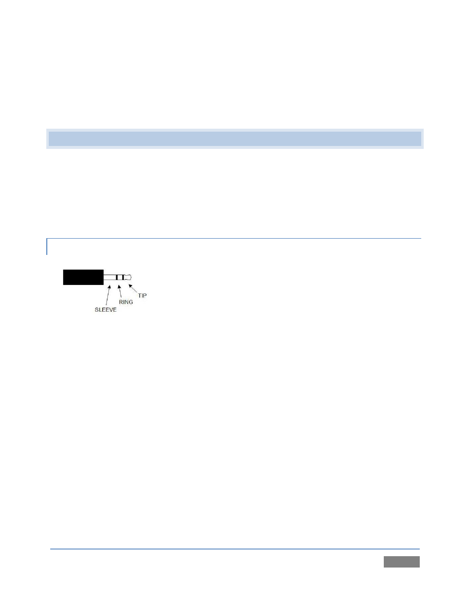
The jacks accept a standard 1.8” (3.5mm) male TRS plug. The
‘TRS’ designation refers to "tip", "ring" and "sleeve", describing
the 3 contacts on the 3 plug (Figure 14).
The tip and ring contacts supply a ‘logic low’ signal when the corresponding tally light is
not lit, and ‘logic high’ when it is.
An external LED may be directly driven by connecting it across either the tip and sleeve,
or the ring and sleeve. The LED anode should be connected to the tip or ring, and its
cathode to the sleeve.
The tip-sleeve contact state is controlled by the Program row selection, corresponding
to the red Tally Light on TriCaster’s faceplate.
The ring-sleeve contact state is controlled by the Preview row selection, corresponding
to a green Tally Light on TriCaster’s faceplate.
Figure 14