Configuration verification, Network requirements, Configuration procedure – H3C Technologies H3C WX6000 Series Access Controllers User Manual
Page 600
49-25
Configuration verification
Radio 2 of AP 1 and radio 2 of AP 2 are in the same load balancing group, and the radio of AP 3
does not belong to any load balancing group. Because load balancing takes effect on only radios in
a load balancing group, AP 3 does not take part in load balancing.
Assume Client 7 wants to associate with AP 2. Because the number of clients associated with AP 2
reaches 5, and the session gap between AP 2 and AP 1 reaches 4, Client 7 is associated with AP
1.
Group-Based Traffic-Mode Load Balancing Configuration Example
Network requirements
As shown in
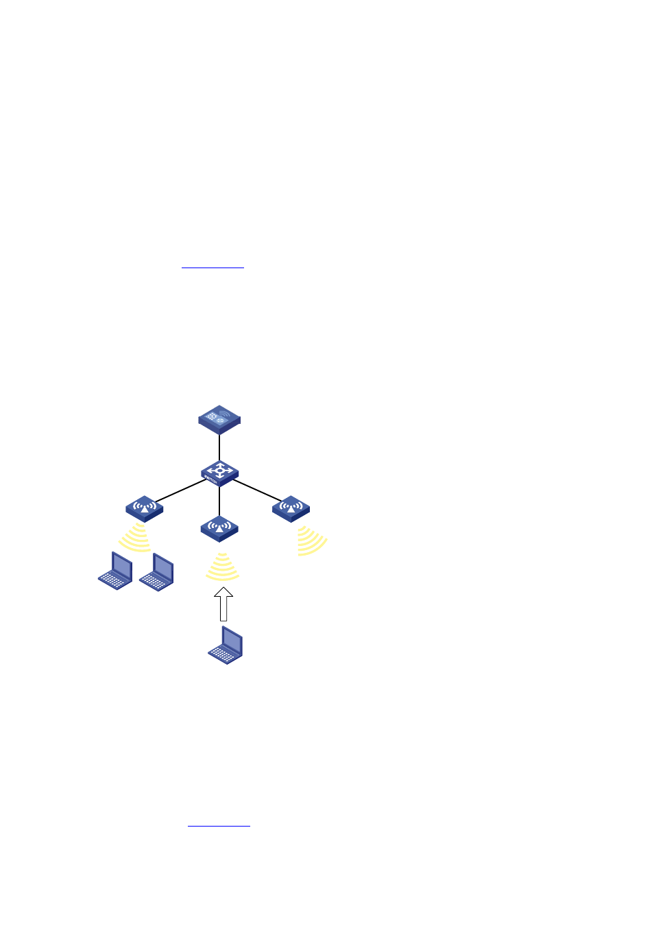
, all APs operate in 802.11g mode. Client 1 and Client 2 are associated
with AP 1, and no client is associated with AP 2 and AP 3.
Configure traffic-mode load balancing on the AC. The maximum traffic threshold is 10% and the
maximum traffic gap is 20%.
Traffic-mode load balancing is required on only radio 2 of AP 1 and radio 2 of AP 2. Therefore, add
them to a load balancing group.
Figure 49-26 Network diagram for group-based traffic-mode load balancing
AC
L2 Switch
AP 1
AP 2
Client 1
Client 2
AP 3
Client 3
Configuration procedure
1) Before configuring load balancing, complete the following task:
Configure AP 1 and AP 2 on the AC to establish a CAPWAP connection between the AC and each
AP. For the related configuration, see Wireless Service.
2) Configure load balancing
Select Advanced > Load Balance from the navigation tree to enter the load balancing configuration
.