Stateful failover configuration example, Network requirements – H3C Technologies H3C WX6000 Series Access Controllers User Manual
Page 608
50-4
Item
Description
Backup VLAN
Set the backup VLAN.
After a VLAN is configured as a backup VLAN, the interface(s) in the VLAN is used
to transmit stateful failover packets.
A device uses VLAN tag+protocol number to identify stateful failover packets,
and broadcasts stateful failover packets to the peer within the backup VLAN.
Therefore, you are not recommended to configure other services (such as voice
VLAN) for a backup VLAN to avoid impact on the operation of stateful failover.
An interface added to the backup VLAN can transmit other packets besides
stateful failover packets.
The lower part of the page displays the current stateful failover configuration.
Table 50-2 Current stateful failover configuration information
Display information
Description
Current Status
Displays the hot backup state of the device.
Stateful Failover Configuration Example
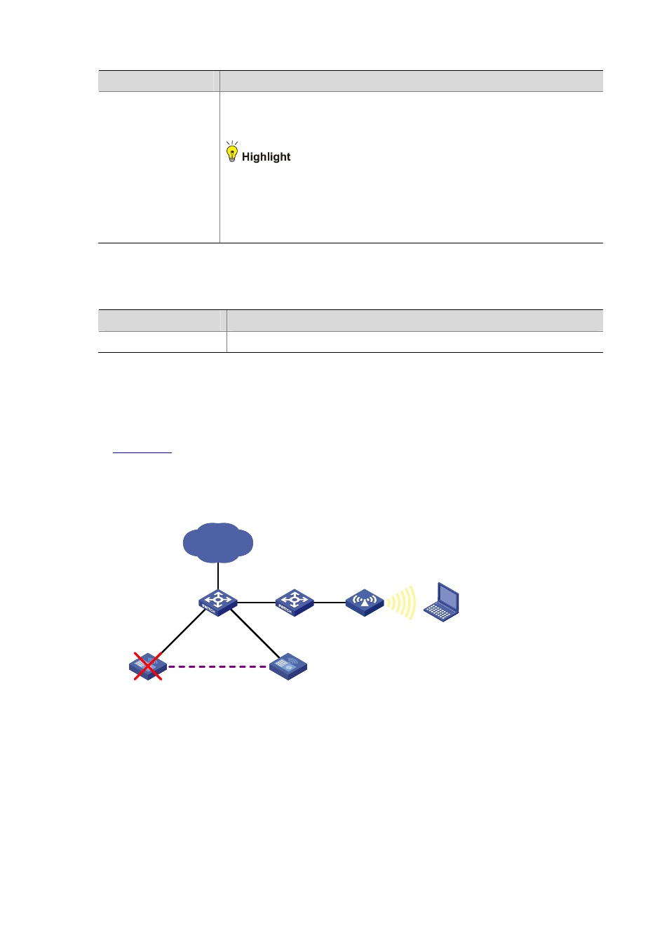
Network requirements
In
, the IP address of VLAN-interface 1 on AC 1 is 8.190.1.60/24, and that on AC 2 is
8.190.1.61/24. In the wireless network, configure AC 1 and AC 2 to backup each other, so that when
one device fails, the other device takes over the services to ensure portal service continuity.
Figure 50-5 Stateful failover network diagram
AC 1
8.190.1.60/24
Internet
Host
AC 2
8.190.1.61/24
Failover link
AP
VLAN 2
GE1/0/2
Untagged VLAN: 1
Tagged VLAN: 2
GE1/0/2
Untagged VLAN: 1
Tagged VLAN: 2