Configuration verification, Wireless location configuration example, Network requirements – H3C Technologies H3C WX6000 Series Access Controllers User Manual
Page 602: Configuration procedure, Wireless location configuration example -27
49-27
Configuration verification
Radio 2 of AP 1 and radio 2 of AP 2 are in the same load balancing group, and the radio of AP 3
does not belong to any load balancing group. Because load balancing takes effect on only radios in
a load balancing group, AP 3 does not take part in load balancing.
Assume Client 3 wants to associate with AP 1. Because the maximum traffic threshold and traffic
gap have been reached on AP 1, Client 3 is associated with AP 2.
Wireless Location Configuration Example
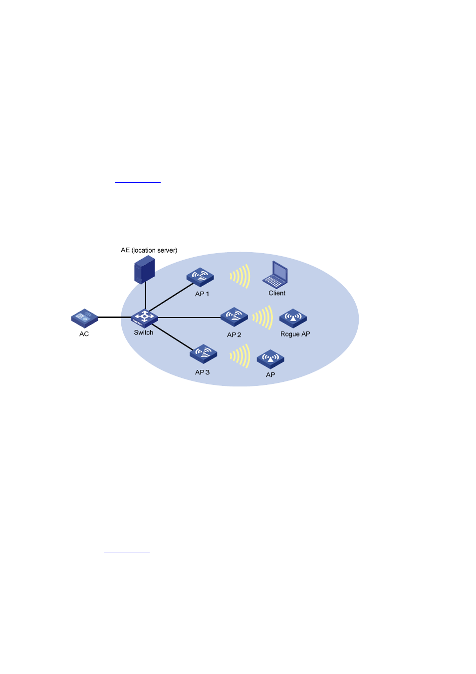
Network requirements
As shown in
, AP 1, AP 2, and AP 3 work in monitor mode, and send the collected tag and
MU messages to an AE (the location server), which performs location calculation and then sends the
data to the graphics software. You can get the location information of the rogue AP, APs, and clients by
maps, forms or reports.
Figure 49-29 Network diagram for configuring wireless location
Configuration procedure
1) Configure the AE.
Configure the IP addresses of AP 1, AP 2, and AP 3 on the AE, or select broadcast for the AE to
discover APs.
Perform configuration related to wireless location on the AE.
2) On the AC, configure AP 1, AP 2, and AP 3 to work in monitor mode.
AP 1, AP 2, and AP 3 are configured similarly, and thus this section only describes how to configure AP
1 for illustration.
# Create AP 1.
Select AP > AP Setup from the navigation tree, and click New to enter the page for adding an AP, as
shown in
.