Iqpump functions – Yaskawa iQpump Micro User Manual
Page 108
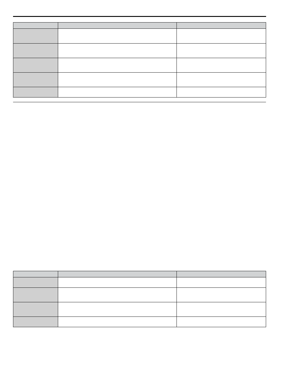
No.
Parameter Name
Setting Values
L5-01
Number of Auto Restart Attempts
Default: 5
Min.: 0
Max.: 10
L5-04
Fault Reset Interval Time
Default: 20.0 s
Min.: 10.0
Max.: 3600.0
P1-06
Minimum Pump Speed
Default: 40.0 Hz
Min.: 0.0
Max.: [E1-04]
P5-02
HAND Reference
Default: 40.0 Hz
Min.: 0
Max.: [E1-04]
P5-04
HAND Key Function Selection
Default: 1
Range: 0, 1
u
iQpump Functions
n
Low City or Low Suction Inlet Pressure
This function is used with low suction inlet pressure switches on pressure booster systems for buildings that get their main
water supply from a municipality. This pressure switch enables and disables the pump system when the inlet supply is at a
low demand and when running the pump system in this condition will cause damage.
An inlet pressure switch is wired directly into the drive using one of the digital input terminals. If the pressure switch is active
and sufficient pressure is available, the drive system will operate normally. If the pressure switch indicates that incoming
pressure is too low, the drive will take the following actions:
• The drive will be forced into a sleep-like state (coast to stop).
• Any drives staged in multiplex mode will immediately coast to stop.
• The selected alarm “Low City Pressure”, “Low Suction Pressure”, or “Low Water In Tank” will be displayed (determined
by P4-24).
All drives will restart when sufficient pressure returns.
Required Control Wiring
Any one of the multi-function digital inputs (S1 to S7) must be wired and programmed with a low suction inlet pressure switch.
The appropriate terminal parameter (H1-oo) must be to set 73 (Low City Pressure). The action of the switch (normally open /
normally closed) is set in parameter P4-21.
Start Up Procedure
1.
Set all other parameters required for the application such as PID control loop, sleep, motor, and I/O parameters.
2.
Set one digital input for the low suction inlet pressure switch (H1-oo = 73). Wire the switch to this terminal.
3.
Configure the terminal for a normally open / closed switch type using parameter P4-21.
4.
Configure the delay times for activating and removing the alarm in parameters P4-23 and P4-24. This can be used to
stop the drive from frequent cycling when pressure varies greatly.
5.
Select the alarm message that will be displayed when a Low City condition is detected using parameter P4-24. Options
include “Low Cty Pressure”, “Low Suction Pres”, and “Low Watr In Tank”.
Related Parameters, Faults, and Alarms
No.
Parameter Name
Setting Values
P4-21
Low City Input Select
Default: 1
Range: 0, 1
P4-22
Low City On-Delay Time
Default: 10 s
Min.: 1
Max.: 1000
P4-23
Low City Off-Delay Time
Default: 5 s
Min.: 0
Max.: 1000
P4-24
Low City Alarm Text
Default: 0
Range: 0 to 2
4.7 iQpump Presets and Functions
108
YASKAWA TOEP YAIQPM 03B YASKAWA AC Drive - iQpump Micro User Manual