U1 - 11, U1 - 12 – Yaskawa iQpump Micro User Manual
Page 279
No.
(Addr.
Hex)
Name
LCD Display
Description
Analog
Output Level
Unit
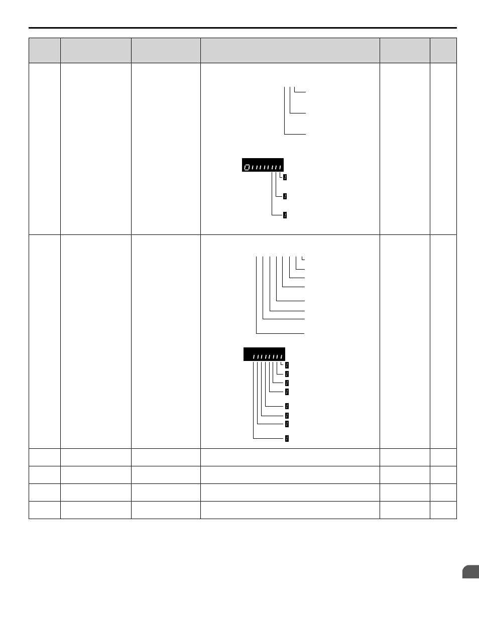
U1-11
(004A)
Output Terminal
Status
Output Term Sts
Displays the output terminal status.
U1 - 11=
00000000
Multi-Function
Digital Output (fault)
(terminal MA/MB-MC)
Multi-Function
Digital Output 1
(terminal P1) enabled
Multi-Function
Digital Output 2
(terminal P2) enabled
1
1
1
Multi-Function
Digital Output (fault)
(terminal MA/MB-MC)
Multi-Function
Digital Output 1
(terminal P1) enabled
Multi-Function
Digital Output 2
(terminal P2) enabled
No signal output
available
–
U1-12
(004B) Drive Status
Int Ctl Sts 1
Verifies the drive operation status.
U1 - 12=
00000000
During run
During zero-speed
During REV
During fault reset
signal input
During speed agree
Drive ready
During alarm
detection
During fault detection
1
1
1
1
1
1
1
1
During run
During zero-speed
During REV
During fault reset
signal input
During speed agree
Drive ready
During alarm
detection
During fault detection
No signal output
available
–
U1-13
(004E)
Terminal A1 Input
Level
Term A1 Level
Displays the signal level to analog input terminal A1.
10 V: 100%
0.1%
U1-14
(004F)
Terminal A2 Input
Level
Term A2 Level
Displays the signal level to analog input terminal A2.
10 V: 100%
0.1%
U1-16
(0053)
Output Frequency after
Soft Starter
SFS Output
Displays output frequency with ramp time and S-curves. Units
determined by o1-03.
10 V: Max
frequency
0.01 Hz
U1-18
(0061)
oPE Fault Parameter
OPE Error Code
Displays the parameter number that caused the oPE02 operation
error.
No signal output
available
–
B.15 U: Monitors
YASKAWA TOEP YAIQPM 03B YASKAWA AC Drive - iQpump Micro User Manual
279
B
Parameter List