Yaskawa iQpump Micro User Manual
Page 109
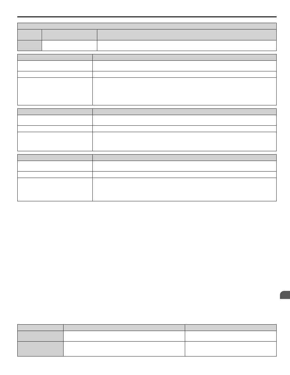
H1 Multi-Function Digital Input Settings
H1-oo
Setting
Function
Description
73
Low City Press
Indicates that sufficient or insufficient pressure is present on the inlet to the pump. Used mainly for pressure
booster situations.
Digital Operator Display
Minor Fault Name
Low City Pressure
(LCP)
Low City Pressure
Cause
Possible Solution
Insufficient pressure is present on the inlet
to the pump.
Shown when P4-24 = 0 and when the digital
input has been active (closed for P4-21 = 0,
or open for P4-21 = 1) for the time set in
P4-22.
• Check pressure switch contact for correct operation.
• Check control wiring to drive terminal strip from pressure switch contact.
• Check to make sure that suction pressure is present by means of a separate measuring device.
Digital Operator Display
Minor Fault Name
Low Suction Pressure
(LSP)
Low Suction Pressure
Cause
Possible Solution
Insufficient suction pressure is present.
Shown when P4-24 = 1 and when the digital input has been active (closed for P4-21 = 0, or open for P4-21
= 1) for the time set in P4-22.
The drive, if running, coasts-to-stop and does not run until the digital input has been inactive for the time
set in P4-22.
Digital Operator Display
Minor Fault Name
Low Water in Tank
(LWT)
Low Water in Tank
Cause
Possible Solution
The water level in the tank is too low.
Shown when P4-24 = 2 and when the digital
input has been active (closed for P4-21 = 0,
or open for P4-21 = 1) for the time set in
P4-22.
• Check pressure switch contact for correct operation.
• Check control wiring to drive terminal strip from pressure switch contact.
• Check to make sure that suction pressure is present by means of a separate measuring device.
• Raise the water level.
n
Current Limit
This function provides a current limit of the pump (motor). The function is designed to prevent long-term overload conditions
of the pump, especially if the motor and drive are oversized compared to the pump. The drive will attempt to limit the output
current by reducing the frequency reference. The frequency is reduced using an internal current PID regulator. When the
Current Limit function is active, the alarm "Current Limit Foldback" or “CUr” will be displayed on the digital operator keypad.
This function will only operate correctly when the drive is connected to a variable torque motor load such as a centrifugal
pump. More specifically, it will only operate if the load is such that output current increases as output frequency increases
(and vice-versa). The current limit function reduces the pump speed to just above the lower value between the minimum pump
speed (P1-06) or the minimum output frequency. If PID mode is enabled (b5-01 > 0), a special limit will be applied to the PID
integrator when output current limit is active to prevent integrator wind-up.
Current Limit Foldback
(CUr)
Start Up Procedure
1.
Set all other parameters required for the application such as PID control loop, sleep, motor, and I/O parameters
2.
Turn on the current limit function by setting Q3-01 to 1 (enabled). The default setting is 0 (disabled).
3.
Set the desired current limit in Q3-02. This value should not exceed the motor, pump or drive ratings. This does not
change the motor (oL1) or drive (oL2) overload functions.
4.
If desired, program a multi-function digital output (H2-oo) to 89 (Output Current Limit) to annunciate the alarm.
Related Parameters
No.
Parameter Name
Setting Values
Q3-01
Output Current Limit Select
Default: 0
Range: 0, 1
Q3-02
Current Limit
Default: 0.0 A
Min.: 0.0
Max.: 1000.0
4.7 iQpump Presets and Functions
YASKAWA TOEP YAIQPM 03B YASKAWA AC Drive - iQpump Micro User Manual
109
4
Start-Up Programming & Operation