Yaskawa iQpump Micro User Manual
Page 122
P1-03 = 200, feedback range = 200 PSI.
If the drive should follow an “Auto Set-Point” set by the HOA keypad: Set b1-01 to “0: Operator” (factory default). The Auto
setpoint can then be entered into the U5-99 monitor parameter in the “-DRIVE-” menu.
Setting 0: Operator (HOA keypad)
Using this setting, the frequency reference can be input by:
• switching between the multi-speed references in the d1-oo parameters.
• entering the frequency reference on the operator keypad.
This selection will also switch PID setpoint to Q1-01.
Setting 1: Terminals (Analog Input Terminals)
Using this setting, an analog frequency reference can be entered from:
• Terminal A1 using a 0 to 10 Vdc signal.
• Terminal A2 using either a 0 to 10 Vdc or a 0/4 to 20 mA signal.
Note:
Terminal A2 supports voltage and current input. The input signal type must be set up by setting DIP switch S1 and adjusting parameter
H3-09.
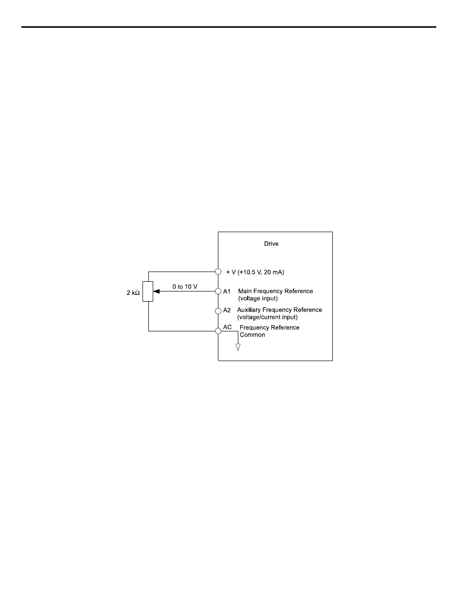
Entering only the main frequency reference:
Using Control Circuit Terminal A1 (0 to 10 Vdc voltage input):
Use a circuit such as the one shown in
or an external 0 to 10 Vdc voltage source like a PLC analog output and
set the input level selection for A1 in parameter H3-02 as desired.
Figure 4.21 Setting the Frequency Reference by Voltage Input
• Using Control Circuit Terminal A2 (0 to 10 Vdc voltage input)
Use the same connection as explained for terminal A1 for terminal A2. Make sure that switch S1 is set to “V” and set the
appropriate signal level for terminal A2 by entering 0 or 1 into parameter H3-09. The terminal A2 function must be set to
frequency bias by entering 0 into parameter H3-10.
• Using Control Circuit Terminal A2 (0/4 to 20 mA current input)
Connect input A2 to an external current source such as the one shown in
. Make sure that switch S1 is set to “I”
and set the appropriate signal level for terminal A2 by entering 2 (4 to 20 mA) or 3 (0 to 20 mA) into parameter H3-09. The
terminal A2 function must be set to frequency bias by entering 0 into parameter H3-10.
4.8 Detailed iQpump Parameter Descriptions
122
YASKAWA TOEP YAIQPM 03B YASKAWA AC Drive - iQpump Micro User Manual