Low voltage wiring for control circuit terminals, Drive short-circuit rating – Yaskawa iQpump Micro User Manual
Page 296
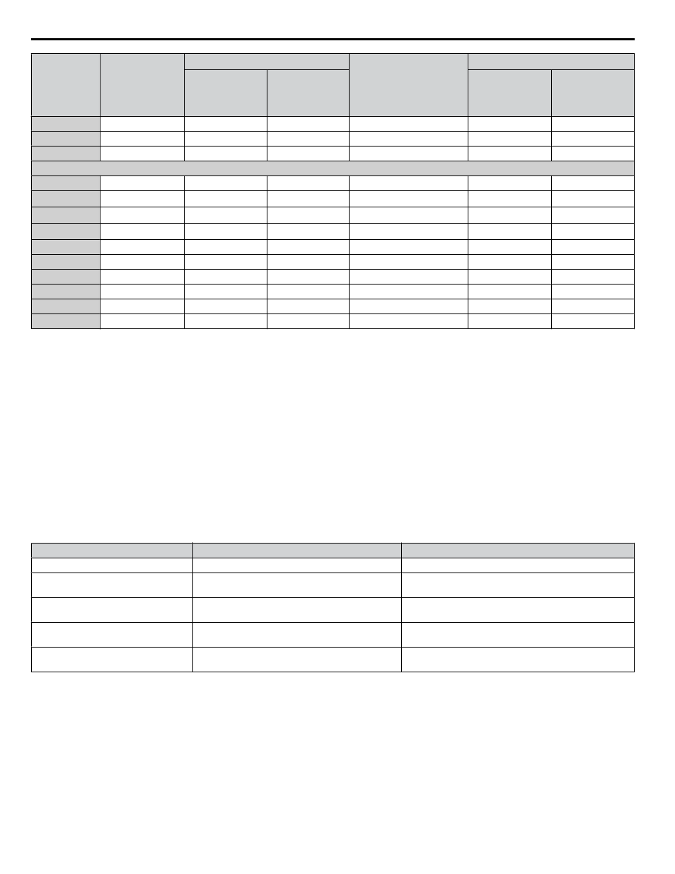
Drive Model
Non-time Delay
Fuse Rating (A)
<1>
Time Delay Fuses
Bussmann
Semiconductor
Fuse Part Number
(Fuse Ampere)
<4>
MCCB
<5>
Class J, T, or CC
Fuse Rating (A)
<2>
Class RK5
Fuse Rating (A)
<3>
Rating (A)
Minimum
Enclosure
Volume (in
3
)
2V0040
–
90
110
FWH-200B (200)
125
1152
2V0056
–
110
150
FWH-200B (200)
150
2560
2V0069
–
125
175
FWH-200B (200)
200
2560
400 V Class Three-Phase Drives
4V0002
6
3.5
3
FWH-40B (40)
15
1152
4V0004
15
<6>
7
8
FWH-50B (50)
15
1152
4V0005
20
<7>
10
10
FWH-70B (70)
15
1152
4V0007
25
<8>
12
15
FWH-70B (70)
20
1152
4V0009
25
15
20
FWH-90B (90)
20
1152
4V0011
30
20
30
FWH-90B (90)
35
1152
4V0018
–
35
45
FWH-80B (80)
50
1152
4V0023
–
40
50
FWH-100B (100)
60
1152
4V0031
–
60
80
FWH-125B (125)
90
1152
4V0038
–
70
90
FWH-200B (200)
110
1152
<1> Maximum 300% of drive input current rating for any Class J, T, or CC fuse except for models 4V0004, 4V0005, and 4V0007.
<2> Maximum 175% of drive input current rating for any Class J, T, or CC fuse.
<3> Maximum 225% of drive input current rating for any Class RK5 fuse.
<4> When using semiconductor fuses, Bussmann FWH are required for UL compliance.
<5> Maximum MCCB Rating is 15 A or 200% of drive input current rating, whichever is larger. MCCB voltage rating must be 600 Vac or greater.
Additionally, when using MCCBs for protection, the drive must be installed in a ventilated enclosure with minimum volume according the “Minimum
Enclosure Volume” column.
<6> Model 4V0004 requires Mersen (Ferraz) part number A6T15 for compliance.
<7> Model 4V0005 requires Mersen (Ferraz) part number A6T20 for compliance.
<8> Model 4V0007 requires Mersen (Ferraz) part number A6T25 for compliance.
n
Low Voltage Wiring for Control Circuit Terminals
Wire low voltage wires with NEC Class 1 circuit conductors. Refer to national state or local codes for wiring. The external
power supply shall be a UL-Listed Class 2 power source or equivalent.
Table C.6 Control Circuit Terminal Power Supply
Input / Output
Terminal Signal
Power Supply Specifications
Multi-function photocoupler output
P1, P2, PC
Requires class 2 power supply
Multi-function digital inputs
S1, S2, S3, S4, S5, S6, S7, SC
Use the internal power supply of the drive. Use class 2 for
external power supply.
Multi-function analog inputs
A1, A2, AC
Use the internal power supply of the drive. Use class 2 for
external power supply.
Pulse train input
RP
Use the internal LVLC power supply of the drive. Use class
2 for external power supply.
Pulse train output
MP
Use the internal LVLC power supply of the drive. Use class
2 for external power supply.
n
Drive Short-Circuit Rating
This drive has undergone the UL short-circuit test, which certifies that during a short circuit in the power supply the current
flow will not rise above 31,000 amps maximum at 240 V for 200 V class drives and 480 V for 400 V class drives.
• The MCCB and breaker protection and fuse ratings shall be equal to or greater than the short-circuit tolerance of the power
supply being used.
• Suitable for use on a circuit capable of delivering not more than 31,000 RMS symmetrical amperes for 240 V in 200 V class
drives (up to 480 V for 400 V class drives) motor overload protection.
C.1 UL Standards
296
YASKAWA TOEP YAIQPM 03B YASKAWA AC Drive - iQpump Micro User Manual