Route cables through cable glands – Yaskawa iQpump Micro User Manual
Page 68
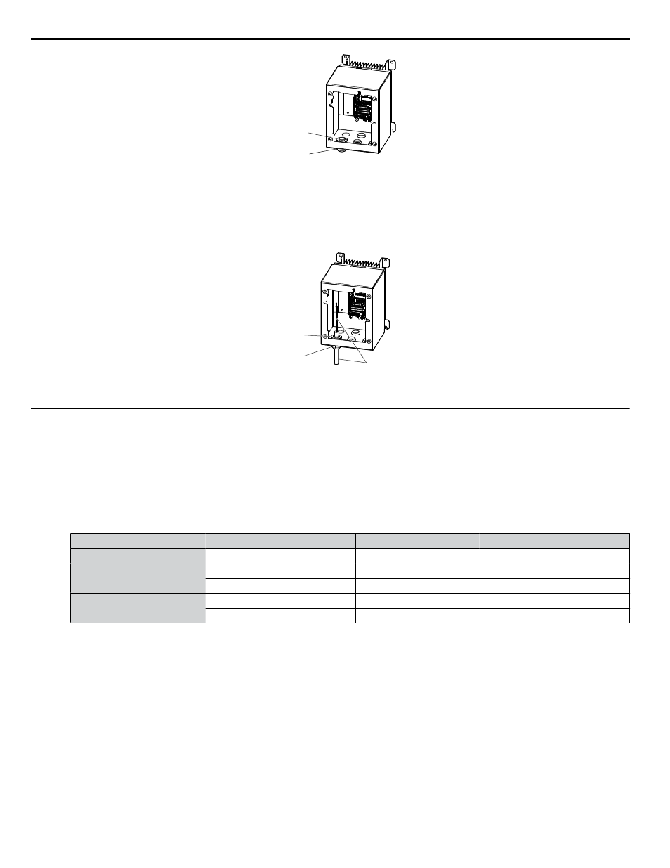
Cable gland
(Locknut)
Cable gland
(Body)
Figure 3.12 Inserting the Cable Glands
n
Route Cables Through Cable Glands
Route the cables through the cable glands then tighten the cable gland caps to complete preparation for main circuit and control
circuit wiring.
Cable gland
(Locknut)
Cable gland
(Body)
Cable
Figure 3.13 Cable Routing
u
IP66/NEMA Type 4X Enclosure Front Cover Removal and Installation
NOTICE: Do not attempt to disassemble the protective enclosure surrounding the drive. The protective enclosure is constructed as a single
piece to include the heatsink. Attempting to disassemble the enclosure may void the protective integrity of the enclosure.
1.
Loosen the 4 bolts that attach the enclosure front cover in place, gently move the front cover away from the enclosure.
Press firmly on the digital operator cable connector release tab to disconnect the cable from port CN1 on the drive,
then remove the front cover.
Table 3.2 IP66/NEMA Type 4X Enclosure Front Cover Installation Bolt Size and Torque
Voltage Class
Drive Model
Installation Bolt Size
Tightening Torque N
•m (lb-in)
Single-Phase 200 V Class
BV0001G to BV0012G
M5
2.0 to 2.5 (17.7 to 22.1)
Three-Phase 200 V Class
2V0001G to 2V0020G
M5
2.0 to 2.5 (17.7 to 22.1)
2V0030G to 2V0069G
M6
5.4 to 6.0 (47.8 to 53)
Three-Phase 400 V Class
4V0001G to 4V0011G
M5
2.0 to 2.5 (17.7 to 22.1)
4V0018G to 4V0038G
M6
5.4 to 6.0 (47.8 to 53)
3.4 Preparing IP66/NEMA Type 4X Enclosure Drives for Wiring
68
YASKAWA TOEP YAIQPM 03B YASKAWA AC Drive - iQpump Micro User Manual