Yaskawa iQpump Micro User Manual
Page 124
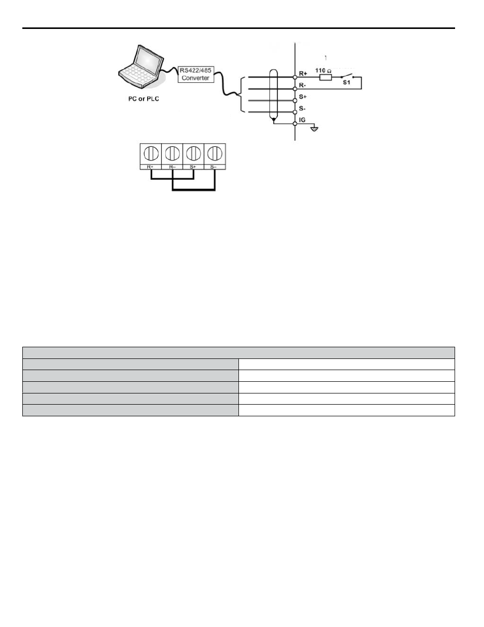
Figure 5.4
RS-485 Communication Connection
Modbus RTU Communications
RS-422/RS-485
19.2 Kbps
Terminating
Resistor
Figure 4.24 PC or PLC Connection Diagram
Setting 3: Option card
This setting requires entering the frequency reference via an option board plugged into connector CN5 on the drive control
board. Consult the option board manual for instructions on integrating the drive with the communication system.
Note:
If the frequency reference source is set for Option PCB (b1-01 = 3), but an option board is not installed, an oPE05 Operator Programming
Error will be displayed on the digital operator and the drive will not run.
To setup the drive to receive the “Auto Setpoint” for a network communication option card, set b1-01 to “3: Option PCB”,
and plug a supported communication option card into the drive control PCB. Consult the manual supplied with the option for
instructions on integrating the drive into the network system.
Setting 4: Pulse Train Input
This setting requires a pulse train signal to terminal RP to provide the frequency reference. Follow the directions below to
verify that the pulse signal is working properly.
Pulse Train Input Specifications
Response Frequency
0.5 to 32 kHz
Duty Cycle
30 to 70%
High Level Voltage
3.5 to 13.2 V
Low Level Voltage
0.0 to 0.8 V
Input Impedance
3 kΩ
Verifying the Pulse Train is Working Properly
• Set b1-01 to 4 and set H6-01 to 0.
• Set the H6-02 to the pulse train frequency value that equals 100% of the frequency reference.
• Enter a pulse train signal to terminal RP and check for the correct frequency reference on the display.
n
b1-02: Run Command Selection 1
Determines the Run command source 1 in AUTO Mode.
The drive comes factory programmed for Start and Stop from the keypad, but the user can program the drive to receive a Run
command from four different inputs: digital operator, terminals, serial communications, or an option PCB.
WARNING! Sudden Movement Hazard. Clear personnel, secure equipment, and check sequence and safety circuitry before starting the
drive. Failure to comply could result in death or serious injury from moving equipment.
To set the drive to receive the Run command from the HOA keypad, set b1-02 to “0: Operator,” and the HAND key will be
used to provide the Run command to the drive.
To set the drive to receive the Run command from the external terminals, set b1-02 to “1: Terminals” and initiate an external
Run command by a contact closure between terminals S1 and SN.
Note:
Using the external terminals requires setting the drive to AUTO Mode by pressing the AUTO key.
4.8 Detailed iQpump Parameter Descriptions
124
YASKAWA TOEP YAIQPM 03B YASKAWA AC Drive - iQpump Micro User Manual