Yaskawa Yasnac PC NC User Manual
Page 113
YASNAC PC NC Operating Manual
Chapter 3: HMI Process Operation
3 - 61
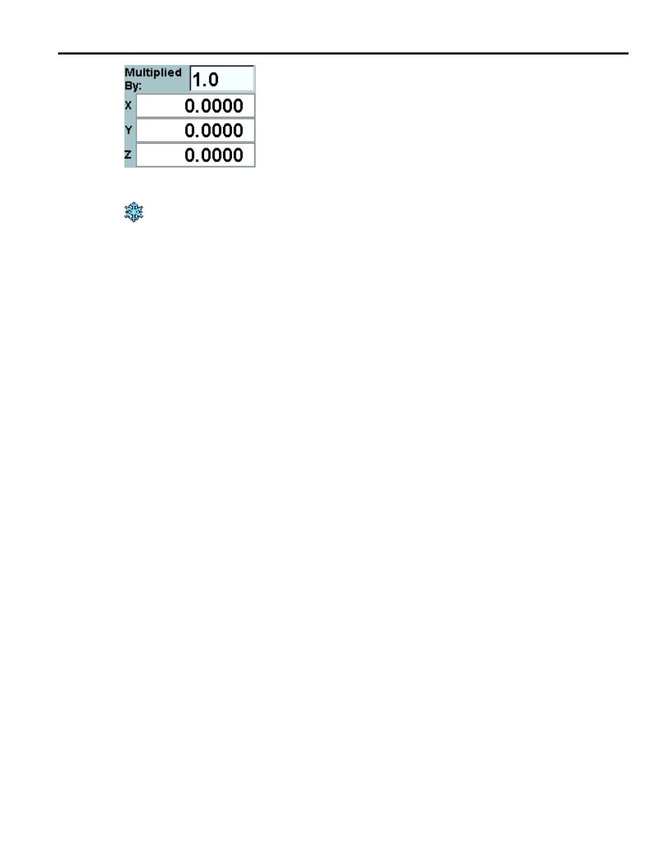
Between the Measure and Machine position displays is a calculated
coordinate display. Above the axis values is a Multiplied By field
that specifies whether the calculated coordinates are double, half, or
some other proportional value of the Measure frame.
The Freeze Result button is used to stop the value of the calculated coordinates from
changing. If the result is not frozen, the display will change whenever the Measure value
changes.
At the bottom of the screen is a table displaying workpiece coordinate systems and a correction
value. The P choice widget above the table is used to specify which P value is in effect for G54 to
G59. There can be 6, 54, or 162 sets of workshift coordinates, corresponding to maximum P val-
ues of 1, 9 and 27 respectively.
Note: Depending on the value of parameter 4012, bit 7, "J" may be displayed instead of "P".
The cells in the table are selectable and their values can be edited in place, unless edit lock is on.
The cells can also be set to one of the axis values of the current machine position. This is done
with the Set X to Machine X (Set Y to Machine Y, etc.) button to the right of the table. The label
on this button changes depending upon which axis, if any, is selected in the table. Set All Using
Machine changes the selected workpiece coordinate system to be the current machine position.
Finding the center of a part:
•
First move the tool to one side of the part.
•
Zero the desired coordinate (or all coordinates) of the Measure frame using the Zero Axis or
Zero All button.
•
Move the machine to the other side of the part.
•
Set the Multiplied By field
to.5.
At this point the calculated coordinates are half the value of
the Measure coordinates.
•
Click on the Freeze Result button so that the calculated coordinates remain constant.
•
Using the handwheel, move the machine until the Measure position display and the calculated
coordinate display are the same for the desired coordinate. The machine is now at the center
of the part for the desired axis.
•
Once this is done, the X, Y, or Z can be set for a frame in the table at the bottom of the screen
by using the buttons to the right of the table. These buttons will replace the specified coordi-
nates for the highlighted frame with the machine position.