Yaskawa Yasnac PC NC User Manual
Page 252
YASNAC PC NC Operating Manual
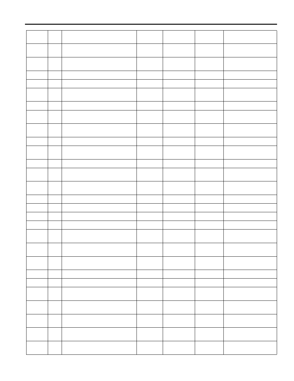
APPENDIX 3: Parameter Tables
A3 - 26
4805
5th axis automatic coordinate setup value
when mm
0.001mm
-999999999
999999999
4815
5th axis automatic coordinate setup value
when inch
0.0001inch
-393700787
393700787
5015
4
5th axis PLC control axis switch over
0
1
5105
5th axis PLC axis control group
0
3
5405
Time from ESP signal rising to base block on
5th axis
msec
0
32767
multiply of 10msec
6000
4
Pitch error compensation 5th axis
0
1
6002
4
No.1 stored stroke limit check 5th axis exe-
cution
0
1
6004
4
Execution of stored stroke limit check for
rotary 5th axis
0
1
6006
4
Axis disconnection 5th axis
0
1
6105
5th axis, pitch error compensation multipli-
cation
0
3
6405
5th axis, pitch error start memory number
0
1151
6415
5th axis, pitch error completion memory
number
0
1151
6425
5th axis, pitch error reference point memory
number
0
1151
6805
5th axis, pitch error compensation intervals
0.001mm
0
999999999
6815
5th axis, second reference point position
0.001mm
-999999999
999999999
6825
5th axis, third reference point position
0.001mm
-999999999
999999999
6835
5th axis, fourth reference point position
0.001mm
-999999999
999999999
6865
5th axis, pitch error compensation stroke
(maximum)
0.001mm
-999999999
999999999
6875
5th axis, pitch error compensation stroke
(minimum)
0.001mm
-999999999
999999999
6885
5th axis, pitch error comp reference point
position
0.001mm
-999999999
999999999
6905
No.1 stored stroke limit 5th axis (+)
0.001mm
-999999999
999999999
6915
No.1 stored stroke limit 5th axis (-)
0.001mm
-999999999
999999999
8000
4
Absolute motor zero return condition 5th
axis
0
1
8001
4
Absolute motor position gap condition 5th
axis
0
1
8405
5th axis, fine adjust amount in zero point set-
ting
-32767
32767
8415
5th axis, position gap distance limit when
power ON
0
32767
8475
5th axis (- to +) roundness irregularity Inte-
gral constant
msec
0
32767
Address
Bit
Description
Register
Units
Minimum
Value
Maximum
Value
Long Description