10 pitch error screen, 10 pitch error screen -80 – Yaskawa Yasnac PC NC User Manual
Page 130
YASNAC PC NC Operating Manual
Chapter 3: HMI Process Operation
3 - 78
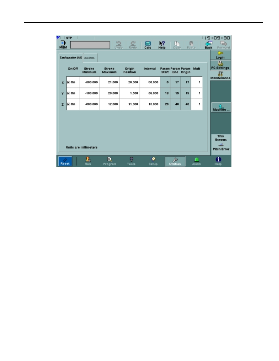
3.7.10 Pitch Error Screen
Fig. 3.7.10.1
Configuration Data Tab of the Pitch Error Screen
The Machine Setup: Pitch Error screen is used to display and set the pitch error compensation
data that is stored in the NC. This screen is only accessible by users at Machinist level or higher.
The Configuration tab controls the range and size of the pitch error intervals. Param Start,
Param End, and Param Origin indicate the corresponding pitch error points for each axis. They
are automatically calculated from Stroke Minimum, Stroke Maximum, Origin Position and
Interval whenever any of these values change. Using the Origin Position, points are added at
positive and negative multiples of Interval within the range from Stroke Minimum to Stroke
Maximum. For all axes there can be a combined total of 1152 pitch error points.
The Axis Data tab, Figure 3.7.10.2 on page 79 shows pitch error points for an individual axis,
which is set using the Axis drop-down menu. Multiply, Origin point, and Origin position are
data reproduced from the Configuration tab for convenience. The table on the right half of the
screen shows all pitch error points for the axis, from Param Start to Param End. For each point,
position (calculated from Configuration tab values) and value are shown. Only Value is editable,
and it can range from -127 to +127. The origin position is highlighted in the table.