18 plc diagnosis screen, 18 plc diagnosis screen -92 – Yaskawa Yasnac PC NC User Manual
Page 142
YASNAC PC NC Operating Manual
Chapter 3: HMI Process Operation
3 - 90
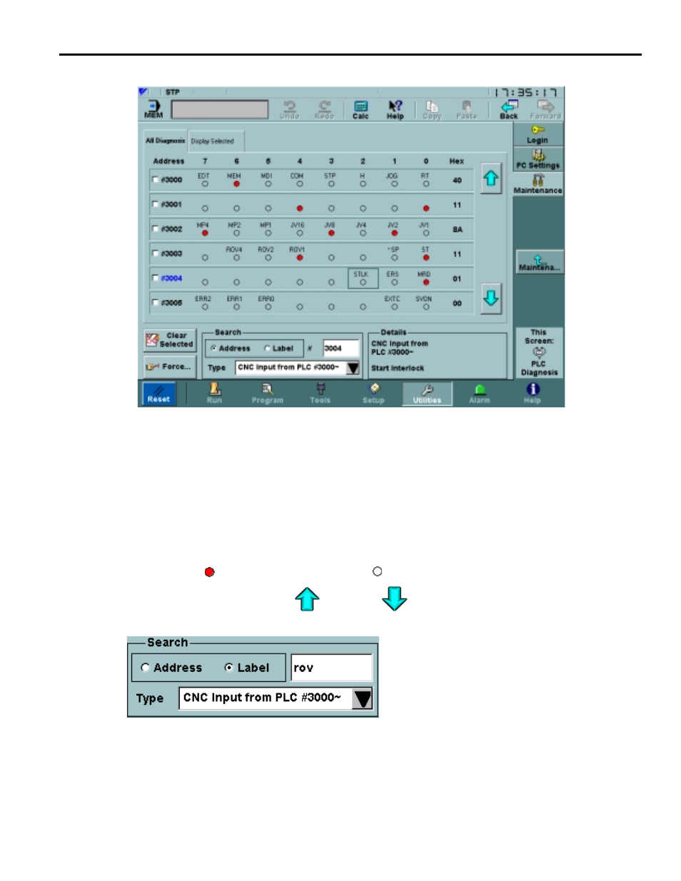
3.7.18 PLC Diagnosis Screen
Fig. 3.7.18.1
The All Diagnosis Tab of the PLC Diagnosis Screen
The Maintenance: PLC Diagnosis screen, shown in Figure 3.7.18.1 on page 90, is used to view
and edit PLC diagnosis parameters. This screen has two tabs: All Diagnosis, which can display
any group of diagnosis parameters, and Display Selected, which shows only diagnosis parame-
ters that are explicitly chosen.
Both tabs have a table that contains byte information. Each line of the table displays the individ-
ual bits for the byte at the address shown in the left-most column. A bit that is on is indicated by a
filled red circle , while an empty black circle denotes a bit that is off. The arrows to the right
of the table are used to scroll up
and down
through the table.
The Search box at the bottom of the PLC
Diagnosis screen controls which items are dis-
played in the All Diagnosis tab. This box is
disabled for the Display Selected tab. The
Type drop-down menu is used to set the
address range of the items to show. The items
within the set address range can be searched
for a string matching the Label of an individual bit, or all PLC diagnosis parameters may be
searched for a specific address. To use this feature, select the search kind, then type a value into
the search field and hit the Enter key. When a match is found, the address is shown in blue. If
necessary, the list will be scrolled so that the address is visible.